In the world of industrial process control, precision is paramount. The ability to accurately modulate the flow of fluids and gases is the bedrock of efficiency, safety, and product quality. At the heart of this precision lies the control valve, and its indispensable partner: the control valve positioner. While a control valve throttles the flow, the positioner ensures it does so with unerring accuracy.
This comprehensive guide will explain the critical role of control valve positioners, delving into their function, the various types available, and the key factors to consider when selecting the right one for your application. We will also explore advanced topics such as diagnostics, split-range control, and best practices for installation and calibration, complete with illustrative diagrams to demystify these complex devices.
What is a Control Valve Positioner and Why is it Necessary?
A control valve positioner is a device used to increase or decrease the air load pressure driving the actuator of a control valve until the valve’s stem reaches a position that is precisely proportional to the setpoint signal from the process controller. In simpler terms, it’s a feedback device that ensures the valve is in the exact position the control system wants it to be.
You might wonder, “Doesn’t the actuator itself control the valve’s position?” While an actuator provides the force to move the valve, it can be susceptible to inaccuracies due to:
- Friction: Friction from the valve’s packing and internal components can cause the valve to stick and move erratically, a phenomenon known as “stiction.”
- Hysteresis: This is the difference in the valve’s position when approaching a setpoint from opposite directions. Actuator and spring inconsistencies can lead to significant hysteresis.
- Varying Differential Pressures: Fluctuations in the pressure of the process fluid can exert varying forces on the valve plug, causing it to deviate from its intended position.
- Actuator Limitations: Actuators alone may not have the power or precision to overcome these forces and achieve fine control.
A positioner overcomes these challenges by creating a closed-loop control system for the valve’s position. It continuously compares the control signal with the actual position of the valve stem and adjusts the actuator’s air supply until the two correspond.
Diagram: Basic Control Valve and Positioner Setup

The Inner Workings: How Control Valve Positioners Function
Understanding the function of a positioner is easier when we break it down into its core components and working principles. While the technology varies, the fundamental concept of comparing a setpoint to a process variable (the valve’s position) and making a corrective action remains the same.
Types of Control Valve Positioners
Control valve positioners are broadly categorized into three main types, each with its own set of advantages, disadvantages, and ideal applications.
1. Pneumatic Positioners
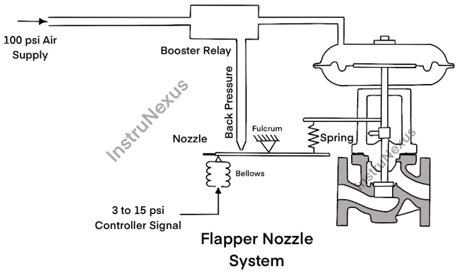
The traditional workhorse of the industry, pneumatic positioners operate entirely on compressed air. They receive a pneumatic control signal (typically 3-15 psi or 0.2-1.0 bar) from a controller and use a clever system of bellows, beams, and flapper-nozzle assemblies to modulate the air supply to the actuator.
Working Principle of a Pneumatic Positioner:
- Signal Reception: The pneumatic control signal from the controller enters a bellows within the positioner.
- Force-Balance Mechanism: The force generated by the control signal bellows is balanced against a feedback spring connected to the valve stem via a mechanical linkage and cam.
- Flapper-Nozzle System: Any imbalance between these forces causes a beam to move, altering the distance between a flapper and a nozzle.
- Air Amplification: This change in the flapper-nozzle gap varies the backpressure in the pneumatic circuit, which is then amplified by a pneumatic relay.
- Actuator Movement: The amplified air pressure is sent to the actuator, causing the valve to move.
- Feedback and Correction: As the valve stem moves, the feedback linkage and cam reposition the feedback spring, bringing the system back into balance at the new desired valve position.
Diagram: Working Principle of a Pneumatic Positioner
Advantages of Pneumatic Positioners:
- Intrinsic Safety: Their purely pneumatic operation makes them inherently safe for use in hazardous and explosive environments where electrical devices would require expensive and complex protection.
- Simplicity and Reliability: With fewer complex components, they are often robust and easy to maintain.
- Low Cost: They are generally the most economical option.
Disadvantages of Pneumatic Positioners:
- Slower Response Time: Compared to their electronic counterparts, they can be slower to react to changes in the control signal.
- Limited Accuracy: Mechanical components are prone to wear and require regular calibration to maintain accuracy.
- No Advanced Diagnostics: They offer no insight into the health and performance of the control valve.
- Air Consumption: They continuously bleed a small amount of compressed air, which can be an operational cost.
2. Electro-Pneumatic (Analog) Positioners
Electro-pneumatic positioners bridge the gap between older pneumatic control systems and modern electronic ones. They accept an electrical control signal (typically 4-20 mA) and convert it into a proportional pneumatic signal to operate the actuator.
Working Principle of an Electro-Pneumatic Positioner:
- Signal Conversion: The 4-20 mA electrical input signal is fed to a current-to-pressure (I/P) converter within the positioner.
- Pneumatic Signal Generation: The I/P converter produces a proportional pneumatic signal (e.g., 3-15 psi).
- Pneumatic Operation: From this point, the operation is very similar to a pneumatic positioner, with the internal pneumatic signal acting on a bellows or diaphragm within a force-balance mechanism to control a pneumatic relay.
- Actuator Control and Feedback: The relay modulates the air to the actuator, and a mechanical feedback linkage ensures the valve reaches the desired position.
Diagram: Working Principle of an Electro-Pneumatic Positioner

Advantages of Electro-Pneumatic Positioners:
- Compatibility: They can be easily integrated into modern Distributed Control Systems (DCS) and Programmable Logic Controllers (PLC) that use analog electrical signals.
- Improved Performance: They generally offer faster response times and better accuracy than purely pneumatic positioners.
Disadvantages of Electro-Pneumatic Positioners:
- Complexity: The addition of the I/P converter adds a layer of complexity.
- Limited Diagnostics: While more advanced than pneumatic positioners, they still lack the sophisticated diagnostic capabilities of digital positioners.
- Calibration: Still require manual calibration.
3. Digital (Smart) Positioners
Digital or “smart” positioners represent the cutting edge of control valve technology. They use a microprocessor to position the valve and offer a wealth of diagnostic information. They accept a digital control signal, often superimposed on a 4-20 mA signal using protocols like HART®, or purely digital signals like FOUNDATION™ Fieldbus or PROFIBUS®.
Working Principle of a Digital Positioner:
- Digital Signal Processing: The microprocessor receives the digital control signal (the setpoint).
- Position Sensing: A non-contact position sensor (often using Hall effect or magnetic resistance technology) continuously monitors the valve stem’s exact position (the process variable).
- Microprocessor Control: The microprocessor compares the setpoint to the process variable and calculates the necessary correction.
- Precise Air Control: The microprocessor controls piezoelectric or solenoid valves to precisely regulate the air pressure to the actuator with minimal air consumption.
- Continuous Feedback: The position sensor provides constant feedback to the microprocessor, ensuring highly accurate and responsive positioning.
Advantages of Digital Positioners:
- Superior Accuracy and Performance: They offer the highest level of precision and responsiveness.
- Advanced Diagnostics: This is their standout feature. They can monitor and report on a wide range of parameters, enabling predictive maintenance.
- Auto-Calibration: Most smart positioners can be calibrated automatically, saving time and ensuring optimal performance.
- Reduced Air Consumption: They only consume air when moving the valve, making them highly efficient.
- Remote Communication: They can be configured, monitored, and diagnosed remotely, reducing the need for personnel to enter hazardous areas.
Disadvantages of Digital Positioners:
- Higher Initial Cost: They are the most expensive type of positioner.
- Complexity: Their advanced features require more technical expertise for setup and troubleshooting.
The Power of Digital Diagnostics: A Deeper Look
The diagnostic capabilities of smart positioners are a game-changer for plant maintenance and reliability. They can perform and record various tests, including:
- Partial Stroke Testing (PST): This is a critical function for emergency shutdown (ESD) valves. A PST allows the valve to be moved a small amount (e.g., 10-20%) without disrupting the process, verifying that it is not stuck and will operate when needed.
- Valve Signature Analysis: A valve signature is a graph that plots the actuator pressure against the valve’s travel. It provides a detailed “fingerprint” of the valve’s performance, revealing issues like friction, stiction, and seat wear. Comparing signatures over time can predict failures before they occur.
Diagram: Valve Signature Analysis Graph
(A graph showing a typical valve signature, with actuator pressure on the y-axis and valve travel on the x-axis. The graph should illustrate the difference between the opening and closing strokes, indicating the level of friction.)
A Special Application: Split-Range Control
Positioners are essential for implementing split-range control strategies. In this setup, a single controller output signal is used to operate two or more control valves. Each valve responds to a specific portion of the controller’s output range.
For example, a controller output of 0-50% might operate a small valve for fine control, while a signal of 51-100% operates a larger valve for high-flow requirements. This is achieved by calibrating the positioners of the two valves to respond to different input signal ranges.
Diagram: Split-Range Control
(A diagram showing a single controller sending a signal to two control valves. The positioner on the first valve is calibrated for 0-50% of the signal, and the positioner on the second valve is calibrated for 51-100%.)
How to Select the Right Control Valve Positioner: A Checklist
Choosing the appropriate positioner is crucial for optimizing your process. Here’s a checklist of key factors to consider:
1. Type of Control Signal:
- Pneumatic (3-15 psi)?
- Analog/Electronic (4-20 mA)?
- Digital (HART®, FOUNDATION™ Fieldbus, PROFIBUS®)?
2. Actuator Type:
- Single-acting (spring-return)?
- Double-acting (air supplied to both sides of the piston)?
- Linear (for globe or gate valves)?
- Rotary (for ball or butterfly valves)?
3. Hazardous Area Classification:
- Does the environment require intrinsically safe or explosion-proof devices? If so, a pneumatic or properly certified digital positioner is necessary.
4. Required Accuracy and Performance:
- Is precise, repeatable control critical to your process? Digital positioners offer the best performance.
- Is a more basic level of control sufficient? A pneumatic or electro-pneumatic positioner may be more cost-effective.
5. Diagnostic Requirements:
- Do you need predictive maintenance capabilities and remote monitoring? A smart positioner is the only choice.
- Are you primarily concerned with basic valve positioning? A simpler model will suffice.
6. Environmental Conditions:
- Will the positioner be exposed to extreme temperatures, vibration, or corrosive atmospheres? Choose a model with a rugged enclosure and appropriate materials.
7. Air Supply Quality:
- Is your instrument air clean, dry, and regulated? Poor air quality can damage positioners, especially more complex models.
8. Cost:
- Consider the total cost of ownership, not just the initial purchase price. The efficiency and predictive maintenance capabilities of a digital positioner can lead to significant long-term savings.
Installation and Calibration: Best Practices for Optimal Performance
Even the best positioner will underperform if not installed and calibrated correctly.
Installation Best Practices:
- Solid Mounting: The positioner should be securely mounted to the actuator to prevent inaccuracies caused by vibration or movement.
- Proper Linkage: The feedback linkage must be connected without any backlash or play to ensure accurate position sensing.
- Correct Air Supply: Use a dedicated filter-regulator to provide a clean, dry, and stable air supply at the manufacturer’s recommended pressure.
- Follow Manufacturer’s Instructions: Always adhere to the specific installation guidelines provided by the positioner manufacturer.
Calibration:
Calibration ensures that the valve’s travel from 0% to 100% corresponds accurately to the control signal range.
- Pneumatic and Electro-Pneumatic Positioners: These typically require manual calibration by adjusting the zero and span settings. This can be a trial-and-error process.
- Digital Positioners: Most smart positioners feature auto-calibration routines. With the push of a button or a command from a handheld communicator, the positioner will automatically stroke the valve and set the correct parameters.
Regularly scheduled calibration checks are essential to maintain performance and account for wear and tear over time.
Conclusion: Hero of Process Control
The control valve positioner is a small but mighty component in the vast landscape of industrial automation. By ensuring that the control valve precisely follows the commands of the control system, it plays a vital role in enhancing process efficiency, improving product quality, and ensuring operational safety.
Whether you opt for the rugged simplicity of a pneumatic positioner, the balanced performance of an electro-pneumatic model, or the advanced intelligence of a digital positioner, understanding their function, types, and selection criteria is the first step toward achieving optimal control in your processes. By investing in the right positioner and following best practices for installation and maintenance, you can empower your control valves to perform at their peak, delivering the precision and reliability your operations demand.