Control Valve Sizing & Selection in the Oil & Gas Jungle
Hey there, fellow instrumentation enthusiasts! Ever stared down a piping and instrumentation diagram (P&ID) and felt a tiny bead of sweat form when the topic of control valves came up? You’re not alone! Selecting and sizing these unsung heroes of the oil and gas industry can feel like navigating a dense jungle. But fear not, because today, we’re hacking through the undergrowth and shedding light on the crucial aspects of control valve sizing and selection.
In the demanding world of oil and gas, where precision and safety are paramount, the right control valve can make all the difference. From maintaining critical process parameters like pressure and flow to ensuring efficient and safe operations, these valves are the workhorses behind the scenes. Choosing the wrong valve? Well, that can lead to everything from process inefficiencies and safety hazards to costly shutdowns and equipment damage.
So, grab your virtual machete, and let’s dive into this comprehensive guide. We’ll break down the key considerations, illustrate concepts with easy-to-understand block diagrams, and present information in a way that feels less like a technical manual and more like a chat with a knowledgeable colleague. Plus, we’ll sprinkle in some SEO goodness to make sure this guide finds its way to those who need it most.
Why is Proper Control Valve Sizing and Selection So Crucial?
Think of a control valve as the throttle of your process. It needs to be just the right size to effectively control the flow of fluids – whether it’s crude oil, natural gas, or various chemicals.
- Accurate Process Control: An appropriately sized valve ensures that the process variables are maintained within the desired operating range, leading to consistent product quality and efficient operations.
- Preventing Cavitation and Flashing: Undersized valves can lead to high velocities and pressure drops, causing damaging phenomena like cavitation (formation and implosion of vapor bubbles) and flashing (liquid turning into vapor).
- Avoiding Oversizing Issues: Conversely, oversized valves often operate close to their closed position, resulting in poor control, instability, and increased wear and tear.
- Energy Efficiency: Correctly sized valves contribute to optimized pressure drops across the system, minimizing energy consumption by pumps and compressors.
- Safety: In critical applications, the right control valve can be a crucial safety barrier, preventing overpressure or runaway reactions.
Key Factors to Consider in Control Valve Sizing and Selection:
Before you even think about picking a valve, you need to gather some crucial information about your process. This is where your detective hat comes on!
Process Fluid Properties: What exactly are you trying to control? Is it a liquid, a gas, or a multiphase mixture? What’s its viscosity, density, temperature, and chemical composition? Corrosive or abrasive fluids will require special materials.
Operating Conditions: What are the normal and extreme operating pressures and temperatures? What’s the required flow rate range – the minimum, normal, and maximum flow you expect?
Pressure Drop: This is the difference in pressure across the valve when it’s open and controlling flow. You’ll need to determine the available pressure drop in your system.
Valve Characteristics: Different valve types have different inherent flow characteristics (e.g., linear, equal percentage, quick opening). The right characteristic depends on the specific control loop requirements.
Actuator Type and Control Signal: How will the valve be operated? Pneumatic actuators are common, but electric and hydraulic actuators also have their place. What type of control signal will be used (e.g., 4-20 mA)?
Turndown Ratio: This is the ratio of the maximum controllable flow rate to the minimum controllable flow rate. You need to ensure the valve can effectively control flow across the entire operating range.
Reliability and Maintenance: Consider the expected service life, maintenance requirements, and availability of spare parts. In the oil and gas industry, downtime can be incredibly costly.
Safety Requirements: Are there specific safety standards or regulations that the valve must meet (e.g., fire-safe design, emergency shutdown capabilities)?
Decoding the Control Valve Sizing Equation (Simplified!)
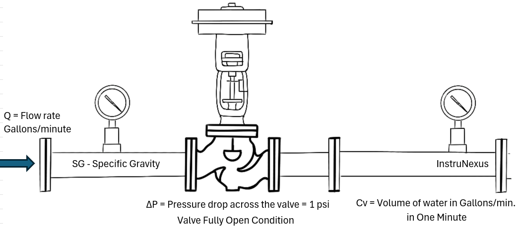
While the full sizing equations can look intimidating (involving specific gravity, temperature corrections, etc.), the fundamental principle revolves around the flow coefficient (Cv). The Cv value is a measure of a valve’s capacity to pass fluid. It’s defined as the volume of water in gallons per minute that will flow through a fully open valve with a pressure drop of 1 psi across the valve.
The basic sizing equation (for liquids) looks something like this:
ΔP/SG)
Where:
- Q = Flow rate (gallons per minute)
- Cv = Flow coefficient (the value we need to find)
- = Pressure drop across the valve (psi)
- SG = Specific gravity of the liquid
Block Diagram: Basic Control Valve Sizing Workflow
Once you have an idea of the required Cv, the next step is choosing the right type of control valve for your application. Here are some common types found in the oil and gas industry:
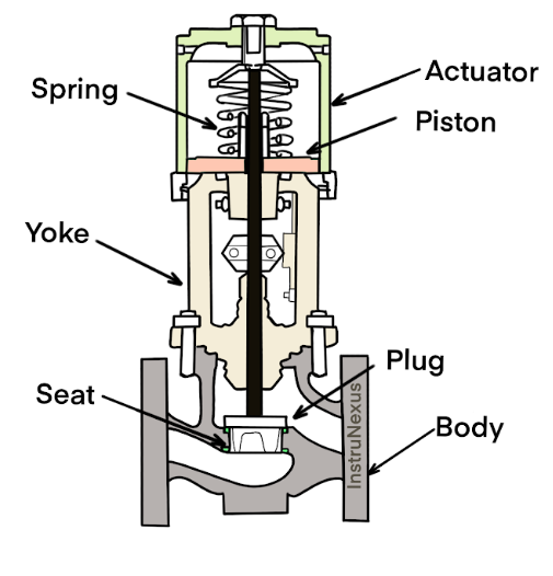
Globe Valves: These are workhorses known for their excellent throttling capability and tight shut-off. They are well-suited for applications requiring precise flow control.
Illustration: Globe Valve (Simplified)
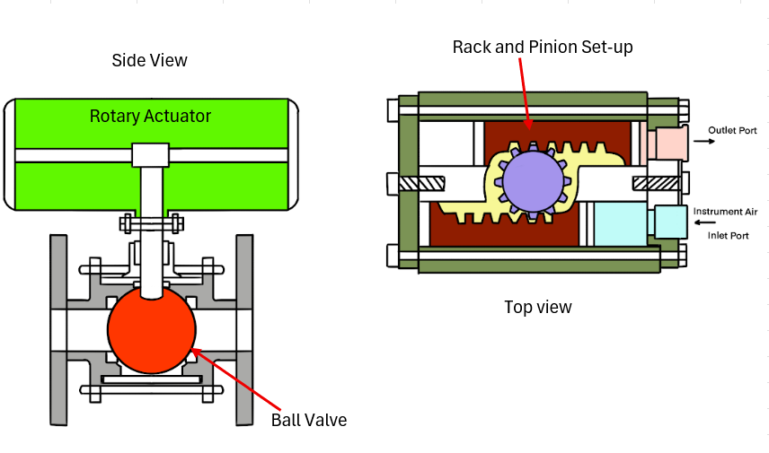
Ball Valves: These quarter-turn valves offer excellent shut-off capabilities and high flow capacity when fully open. Segmented ball valves can also provide good throttling control.
Illustration: Ball Valve (Simplified)
Butterfly Valves: These are lightweight and compact quarter-turn valves suitable for large flow rates and lower pressure applications. They offer good control but may not provide as tight a shut-off as globe or ball valves in all designs.
Illustration: Butterfly Valve (Simplified)

Plug Valves: Similar to ball valves, plug valves use a cylindrical or tapered plug with a bore to control flow. They offer good shut-off and can handle viscous fluids.
Illustration: Plug Valve (Simplified)

Table: Control Valve Type Selection Guide (Humanized)
Beyond Sizing: Smart Selection Considerations
Sizing is just one piece of the puzzle. Here are some other crucial aspects to keep in mind during selection:
Materials of Construction: Choosing materials compatible with the process fluid is critical to prevent corrosion, erosion, and other forms of material degradation. Consider stainless steels, carbon steels, special alloys, and even lined valves for highly aggressive fluids.
Actuator Selection: The actuator provides the force to move the valve trim. Pneumatic actuators are common due to their reliability and speed, but electric actuators are gaining popularity for their precision and reduced air consumption. Hydraulic actuators are used for high-force applications.
Positioners: These devices enhance the accuracy and responsiveness of the control valve by ensuring the valve stem position corresponds precisely to the control signal. They are particularly important for critical control loops.
Block Diagram: Control Valve with Positioner

Noise Considerations: High pressure drops across control valves can generate significant noise. In some cases, special low-noise trim designs or diffusers may be required to meet environmental regulations and protect personnel.
Packing and Seals: These components prevent leakage of the process fluid to the atmosphere. The type of packing and seals must be compatible with the fluid and operating conditions.
Humanized Takeaway: It’s About Finding the Right Partner
Think of sizing and selecting a control valve like finding the right partner for a critical task. You need someone (or something) that understands the job (process conditions), has the right skills and strength (Cv and actuator), and can reliably perform the task day in and day out (reliability and material compatibility).
In Conclusion: Mastering the Art of Control Valve Selection
Control valve sizing and selection in the oil and gas industry is a multifaceted process that requires a thorough understanding of process requirements, valve characteristics, and various operational considerations. By carefully evaluating the factors discussed in this guide, you can move beyond guesswork and make informed decisions that lead to accurate process control, enhanced safety, and efficient operations.
Remember to always consult relevant industry standards, valve manufacturer guidelines, and experienced instrumentation professionals to ensure the correct selection for your specific application.
Stay tuned for more insights and practical tips on instrumentation engineering! And as always, feel free to share your experiences and questions in the comments below. Let’s keep the conversation flowing!
SEO Keywords: Control Valve Sizing, Control Valve Selection, Oil and Gas Industry, Instrumentation Engineer, Cv Calculation, Globe Valve, Ball Valve, Butterfly Valve, Plug Valve, Actuator, Positioner, Process Control, Valve Characteristics, Pressure Drop, Flow Rate.