Controlling Output Devices: Understanding DCS Output Modules
In the intricate world of industrial automation, precision control is paramount. At the heart of this control lies the Distributed Control System (DCS), a powerful platform that orchestrates complex manufacturing and processing operations. While the “brains” of the DCS are the controllers, the “hands” are the output modules. These unsung heroes translate digital commands into physical actions, driving the pumps, valves, motors, and heaters that keep modern industry moving.
This in-depth guide explores the critical role of DCS output modules. We’ll delve into what they are, how they work, the different types you’ll encounter, and how to select the right one for your application. Whether you’re a seasoned control engineer, a technician on the plant floor, or a student of automation, this article will provide a clear understanding of these essential components.
What is a Distributed Control System (DCS)?
Before we can appreciate the output module, we must first understand its home: the Distributed Control System (DCS). Unlike a centralized system where a single computer manages everything (a single point of failure), a DCS distributes control functions across multiple controllers. Each controller, or node, is responsible for a specific process area or unit. This distributed architecture enhances reliability, scalability, and efficiency.
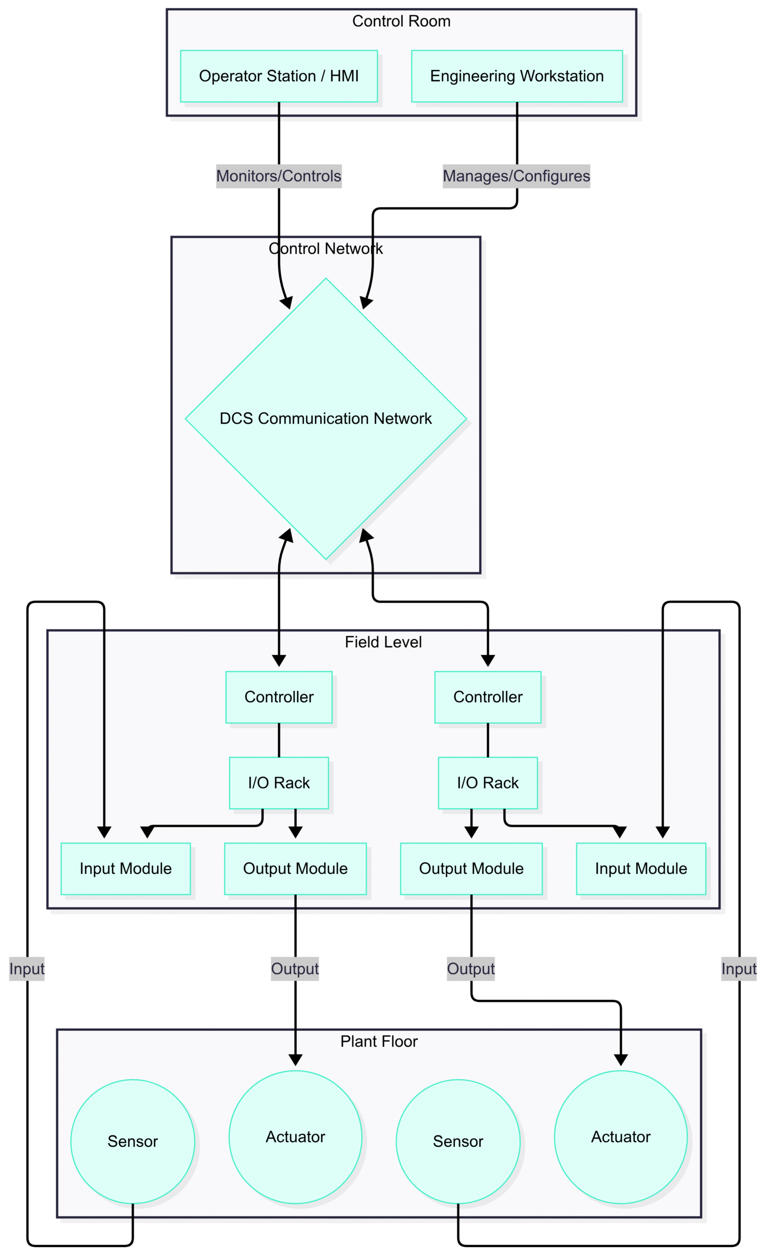
A typical DCS consists of several key components:
Engineering Workstation: Used for configuration, programming, and system diagnostics.
Operator Station (HMI): The Human-Machine Interface where operators monitor and interact with the process.
Controllers: The processing units that execute the control logic.
I/O Modules: The interface between the controller and the field devices (sensors and actuators).
Communication Network: The data highway that connects all the components.
The I/O (Input/Output) modules are the bridge between the digital world of the controller and the physical world of the plant. Input modules bring information in (like temperature, pressure, or level readings), while output modules send commands out.
Here’s a simplified view of a DCS architecture:
The Role of DCS Output Modules
DCS output modules are the executive arm of the control system. Their fundamental job is to convert the low-voltage, low-current digital signals from the DCS controller into the appropriate electrical signals needed to operate various field output devices, also known as actuators.
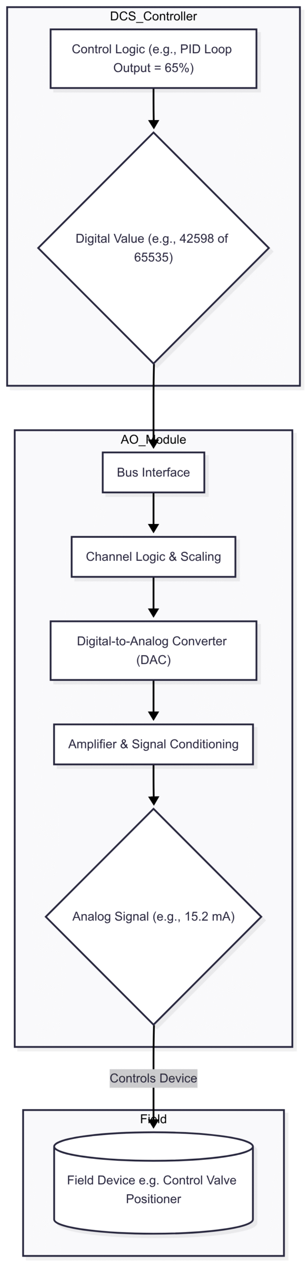
Imagine a chemical reactor where the temperature needs to be maintained at precisely $95^\\circ C$. The controller’s logic determines that a steam valve needs to be opened to 65% to achieve this. The controller sends a digital value representing “65%” to an analog output module. The module then converts this digital value into a corresponding analog signal (e.g., a 15.2 mA current) and sends it to the valve positioner, which physically opens the valve to the desired position.
Without output modules, the controller’s commands would be trapped in the digital realm, unable to influence the physical process. They provide the necessary power amplification, signal conversion, and electrical isolation to safely and reliably control field equipment.
Key Functions of Output Modules
Signal Conversion: Converting digital data from the controller’s bus into analog or digital electrical signals.
Power Amplification: Boosting the low-power controller signal to a level sufficient to drive an actuator like a motor starter or a solenoid valve.
Electrical Isolation: Creating a protective barrier (often using optocouplers or transformers) between the sensitive electronics of the DCS and the harsh, high-power electrical environment of the plant floor. This prevents electrical noise and dangerous voltages from damaging the control system.
Diagnostics: Modern output modules often include diagnostic features, such as open-circuit detection, short-circuit protection, and status feedback, to alert the system of problems with the wiring or the connected device.
Types of DCS Output Modules
Output modules are broadly categorized into two main types based on the nature of the signal they produce: Digital (Discrete) and Analog (Continuous).
1. Digital Output (DO) Modules
Digital Output (DO) modules, also known as discrete output modules, handle on/off signals. They operate like a bank of computer-controlled switches. The controller sends a ‘1’ (On) or ‘0’ (Off) command, and the DO module energizes or de-energizes a specific output channel accordingly.
Applications
DO modules are used to control devices that have two states:
Motors: Starting and stopping via a motor control center (MCC).
Solenoid Valves: Opening and closing on/off valves.
Lamps and Indicators: Turning on alarm lights or status indicators on a control panel.
Relays and Contactors: Energizing coils to switch larger electrical loads.
Alarms: Activating horns or sirens.
How They Work
A controller sends a logic high signal to a specific channel on the DO module. This signal typically activates an optocoupler, which uses light to bridge an electrical gap, ensuring isolation. The phototransistor on the output side of the optocoupler then triggers a switching transistor (like a MOSFET) or a small relay, which completes the circuit to the external field device.

Output Types: DO modules come in various forms, such as relay outputs (for switching AC or DC loads with complete isolation) and solid-state outputs like transistor or Triac (for high-speed, long-life switching of DC or AC loads, respectively).
2. Analog Output (AO) Modules
Analog Output (AO) modules are used for precise, continuous control. Instead of a simple on/off signal, they produce an output signal that can vary over a continuous range, such as 4-20 mA or 0-10 V. This allows for the proportional control of devices.
Applications
AO modules are essential for modulating or throttling devices:
Control Valves: Positioning a valve anywhere between fully closed (0%) and fully open (100%).
Variable Speed Drives (VFDs): Controlling the speed of a motor.
Heaters: Regulating the power output to an electric heating element for precise temperature control.
Louver/Damper Actuators: Adjusting the position of dampers in an HVAC system.
Chart Recorders and Panel Meters: Driving analog displays.
How They Work
The controller sends a digital value (e.g., a 16-bit integer) to the AO module. This digital value is fed into a Digital-to-Analog Converter (DAC) chip. The DAC converts the numerical value into a proportional voltage or current. This signal is then amplified and conditioned before being sent to the field device. The 4-20 mA signal is the most common standard in industrial automation due to its resistance to electrical noise and its inherent ability to detect a broken wire (a 0 mA reading indicates a fault, whereas in a 0-10V system, 0V could be a valid command or a fault).
Selecting the Right DCS Output Module
Choosing the correct output module is a critical step in system design. Making the wrong choice can lead to equipment damage, poor control, or safety hazards. Here are the key factors to consider:
1. Signal Type (Analog vs. Digital)
This is the first and most fundamental decision.
Digital: Do you need to simply turn something on or off? (e.g., start a pump, open a block valve).
Analog: Do you need to proportionally control something? (e.g., adjust a valve opening, change motor speed).
2. Electrical Specifications
Voltage Level: Is the load AC or DC? What is the operating voltage (e.g., 24 VDC, 120 VAC, 230 VAC)? The module must match the load’s voltage requirements.
Current Rating: How much current does the field device draw? The module’s per-channel and total module current rating must exceed the load’s requirements. Overloading a channel can damage the module.
Output Type (for DO):
Relay: Best for high-power AC/DC loads or when complete electrical isolation is needed. They are slower and have a finite mechanical life.
Transistor (Solid-State): Best for low-power DC loads requiring high-speed switching and long life (e.g., driving PLC inputs, small indicators).
Triac (Solid-State): Used for switching AC loads. Faster and longer-lasting than relays but may have a small leakage current when “off.”
Signal Range (for AO): Does the field device require 4-20 mA, 0-20 mA, 0-10 V, or another standard? The 4-20 mA standard is most common for its noise immunity and fault detection capabilities.
3. Channel Count and Density
How many output devices do you need to control? Modules are available with various channel counts (e.g., 4, 8, 16, or 32 channels). High-density modules save space in the control cabinet but may have lower power ratings per channel.
4. Isolation
Channel-to-Channel Isolation: Each channel is electrically isolated from every other channel. This is crucial for applications where different channels are connected to equipment with different power sources or ground references. It prevents ground loops and cross-talk.
Group Isolation: Channels are isolated in small groups (e.g., groups of 4 or 8). This is a less expensive option suitable when all devices in a group share a common power source.
Module Isolation: The entire group of channels is isolated from the DCS backplane but not from each other.
5. Special Features and Diagnostics
Fusing: Does the module have individual fuses per channel to protect against overcurrent events? Are the fuses replaceable?
Open-Circuit Detection: Can the module detect if the wire to the field device is broken? This is an inherent feature of 4-20 mA loops but may be a special feature on other module types.
Short-Circuit Protection: Does the module automatically shut down a channel in case of a short circuit to prevent damage?
HART Passthrough: For analog modules, does it support HART (Highway Addressable Remote Transducer) protocol? This allows digital configuration and diagnostic data to be superimposed on the analog signal, enabling smart device management.
Fail-Safe State: How does the module behave if it loses communication with the controller or loses power? Outputs can be configured to fail-open (de-energize), fail-closed (energize), or hold the last known value. This is a critical safety consideration.
6. Environmental Considerations
Will the module operate in an extreme temperature range, high humidity, or a corrosive atmosphere? Ensure the module’s environmental specifications are suitable for the installation location. For hazardous areas (e.g., explosive atmospheres), you must use Intrinsically Safe (IS) rated modules or appropriate isolation barriers.
Real-World Applications and Best Practices
Let’s look at a practical example: controlling a simple tank filling process.
Inlet Valve: This is an on/off solenoid valve. A Digital Output (DO) module is used to open it when the tank is empty and close it when full. A 24 VDC transistor output module is a common choice.
Outlet Control Valve: This is a modulating valve that controls the flow out of the tank to the next process stage. An Analog Output (AO) module is required to precisely position this valve. A 4-20 mA output signal is sent to the valve’s electro-pneumatic positioner.
Agitator Motor: This motor needs to be turned on when the tank is being filled. A DO module energizes the coil of a motor contactor in the MCC, which then switches the high-power three-phase supply to the motor. A relay output DO module is ideal here to handle the higher voltage/current of the contactor coil.
High-Level Alarm: A horn and a flashing beacon are activated if the level gets too high. These are controlled by separate channels on a DO module.
Best Practices for Implementation
Read the Manual: Always consult the manufacturer’s documentation for the specific module. Pay close attention to wiring diagrams and specifications.
Proper Grounding: Ensure proper grounding of the modules, cabinets, and field devices to minimize electrical noise.
Wire Sizing and Shielding: Use the correct gauge wire for the current load and distance. For analog signals, always use shielded, twisted-pair cable to protect against electromagnetic interference (EMI), and land the shield at one end only (typically the source/DCS end).
Power Segregation: Physically separate low-voltage signal wiring from high-voltage power wiring in cable trays and cabinets to prevent noise induction.
Label Everything: Clearly label all terminals, wires, and modules. This is invaluable during troubleshooting and maintenance.
Test Thoroughly: During commissioning, thoroughly test each output channel. Verify that the correct device activates and that analog signals are producing the correct physical response (e.g., use a multimeter in series to check the 4-20 mA current).
Conclusion: The Power of Control
DCS output modules are the fundamental link between a controller’s logic and the physical machinery of a plant. They are the workhorses of industrial automation, tirelessly and reliably converting millions of digital commands into tangible actions every day. By understanding the distinction between digital and analog outputs, their underlying working principles, and the critical criteria for selection, engineers and technicians can design and maintain control systems that are safe, efficient, and robust.
As technology evolves, we see smarter modules with more advanced diagnostics, higher densities, and better integration with fieldbus technologies. However, their core mission remains the same: to provide precise, reliable control over the output devices that drive our modern world. The next time you see a complex industrial process running smoothly, remember the silent, critical work being done by the output modules inside the control cabinet.
Frequently Asked Questions (FAQ)
Q1: What is the difference between a PLC output module and a DCS output module? A1: Functionally, they are very similar. Both convert controller signals to drive field devices. The main difference often lies in the context of the system. DCS platforms are typically used for large-scale, process-oriented applications (like oil refineries or power plants) and often feature higher levels of redundancy, integrated diagnostics, and system-wide databases. PLC-based systems are often used for smaller-scale, discrete machine control. However, the lines are blurring as modern PLCs (often called PACs – Programmable Automation Controllers) gain more process control capabilities.
Q2: What does it mean for an output to be “sourcing” or “sinking”? A2: This terminology applies to DC digital output modules. A sourcing output module provides the positive voltage (+VDC) to the load. The load is connected between the output terminal and the common/ground. A sinking output module provides the connection to ground (0 VDC) for the load. The load is connected between a positive voltage source and the output terminal. You must match the module type (sourcing/sinking) to the type of input module it is connected to or the requirements of the field device.
Q3: Can I connect multiple devices to a single output channel? A3: It’s generally not recommended for control applications, as it complicates troubleshooting and can lead to overloading the channel. If you connect multiple devices, you must ensure their combined current draw does not exceed the channel’s maximum rating. For safety-critical devices or important control loops, each device should have its own dedicated output channel.
Q4: What is “loop power”? A4: In a 4-20 mA analog circuit, “loop power” refers to the power supply that drives the current loop. Some AO modules can provide this power themselves (a “4-wire” or “active” output). More commonly, an external 24 VDC power supply is used, and the AO module simply regulates the current in the loop provided by that external supply (a “2-wire” or “passive” configuration relative to the field device).
Q5: What is a fail-safe state and why is it important? A5: A fail-safe state is the pre-determined state an output will go to in the event of a failure (e.g., loss of power or communication). This is a critical safety feature. For example, a valve that supplies fuel to a burner should “fail-closed” (shut off) to prevent a dangerous situation. A valve that provides cooling water might need to “fail-open” to prevent overheating. The fail-safe state for each output must be carefully determined during a process hazard analysis.