The Coriolis Mass Flow Meter: A Comprehensive Technical Review of Principles, Design, and Industrial Application
The Coriolis Measuring Principle: A Direct Approach to Mass Flow
The Coriolis mass flow meter represents a paradigm shift in fluid measurement, distinguished from nearly all other technologies by its unique ability to measure mass flow directly and independently of fluid properties. This capability is not an incremental improvement but a fundamental departure rooted in the principles of motion mechanics. Whereas traditional meters infer mass flow from secondary properties like velocity or volumetric displacement—requiring compensation for process variables such as pressure, temperature, and density—the Coriolis meter’s output is a direct and linear function of the mass passing through it. Understanding this foundational principle is essential to appreciating its exceptional accuracy, versatility, and role as a multivariable process instrument.
The Physics of the Coriolis Effect: From Planetary Motion to Process Piping
The operational basis of the meter is the Coriolis effect, an inertial force that acts upon an object moving within a rotating frame of reference. This phenomenon is most commonly illustrated on a planetary scale, where it explains the clockwise rotation of hurricanes in the Southern Hemisphere and counterclockwise rotation in the Northern Hemisphere. As air masses (objects) move across the rotating Earth (the frame of reference), their paths appear to deflect.
In a Coriolis meter, this principle is ingeniously scaled down and applied within an oscillating tube system. Instead of a continuously rotating planet, the meter’s flow tube (or tubes) is electromagnetically actuated to vibrate, typically at its natural resonant frequency. This rapid, controlled oscillation creates the moving frame of reference. The fluid passing through the tube is the mass in motion. As this mass is forced to conform to the tube’s vibration, it experiences the Coriolis effect, resulting in a measurable force that is the basis of the flow measurement.
From Force to Measurement: The Mechanics of an Actuated System
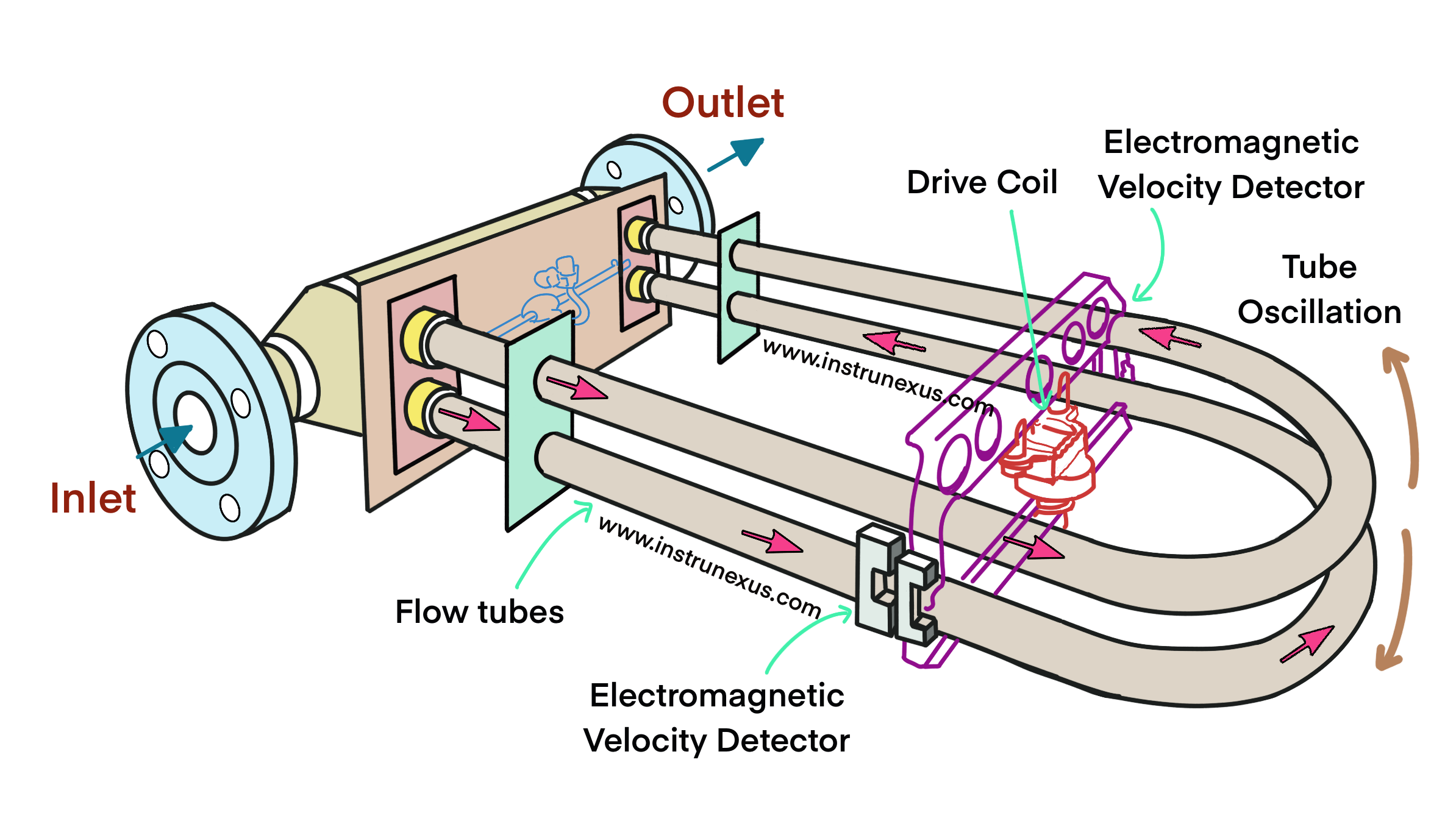
A Coriolis meter’s sensor assembly consists of several key components working in concert. An electromechanical drive coil, or exciter, is typically mounted at the center of the flow tube assembly. This driver imparts a force that stimulates the tube(s) to oscillate in a sinusoidal motion, much like the tines of a tuning fork. A feedback circuit ensures the oscillation is maintained at the tube’s natural resonant frequency with minimal power input.


Positioned at the inlet and outlet sections of the tube assembly are two electromagnetic pickoff sensors. These sensors continuously monitor the motion of the tubes and generate a corresponding sine wave voltage signal. In a “no-flow” condition, with the tube filled with a static fluid, the system is perfectly balanced. The tubes vibrate symmetrically, and the sine waves produced by the inlet and outlet pickoff sensors are identical and perfectly in phase with each other.
The Genesis of the Flow Signal: Phase Shift and Mass Flow Proportionality
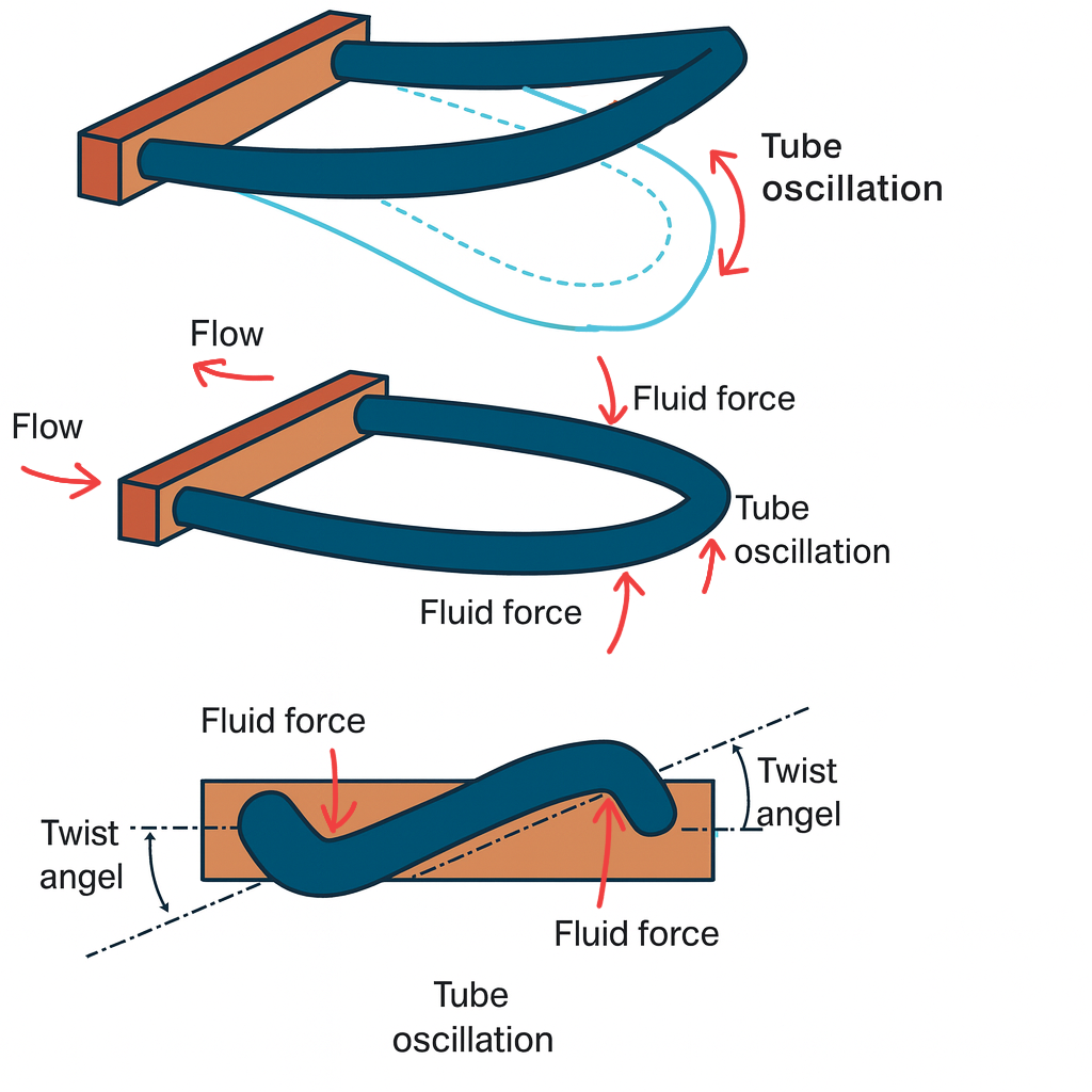
The introduction of fluid flow disrupts this symmetry. As the fluid enters the vibrating tube, it is forced to accelerate and take on the vertical momentum of the tube’s motion. The fluid’s inertia resists this acceleration, exerting a downward force on the inlet side of the tube. Conversely, as the fluid travels toward the outlet, it must be decelerated. Its inertia resists this change as well, exerting an upward force on the outlet side of the tube.
These opposing forces, which act simultaneously during each oscillation cycle, induce a microscopic but measurable twisting motion in the flow tube. This twist causes the inlet side of the tube to lag behind the overall vibration, while the outlet side leads it. The pickoff sensors detect this temporal displacement as a phase shift between their respective sine wave signals. This time difference, often referred to as Delta-T (Delta t), is the raw measurement signal of the meter.
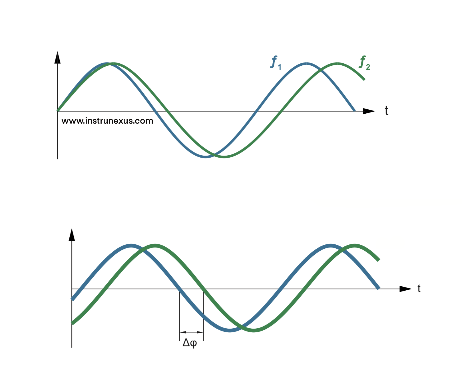
Critically, the magnitude of the Coriolis forces, and therefore the degree of tube twist and the resulting phase shift, is directly and linearly proportional to the mass flow rate (m) of the fluid. It is a function of the mass of the fluid molecules, not their volume or spacing. This direct relationship is the cornerstone of the technology’s power, as it provides a true mass measurement independent of the fluid’s physical properties.
The Multivariable Advantage: Simultaneous Density and Temperature Measurement
Beyond mass flow, the Coriolis meter’s design allows it to measure two other process variables directly and independently, transforming it from a simple flow meter into a powerful process analyzer.
Density Measurement
The flow tubes are designed to vibrate at their natural resonant frequency, a characteristic determined by the tube’s geometry, its material’s stiffness, and the total mass of the system (the tube itself plus the fluid it contains). The geometry and material properties are constant for a given meter. Therefore, the only variable that can alter the total mass within the fixed volume of the tubes is the density of the fluid passing through them.
The meter’s transmitter continuously monitors this resonant frequency. A denser fluid increases the total mass of the system, causing the resonant frequency to decrease. A less dense fluid decreases the total mass, causing the frequency to increase. This direct relationship allows the meter to calculate the fluid’s density with high precision. This density measurement is highly reliable for liquids but is generally not used for gas measurement in fiscal applications, as the low density of gases falls outside the acceptable accuracy range for such purposes.
Temperature Measurement
Integral to every Coriolis sensor is a Resistance Temperature Detector (RTD) mounted directly onto the surface of the flow tube. Its primary purpose is not to provide a process temperature reading for the user, although this value is available. Instead, its critical function is to provide real-time compensation for temperature-induced changes in the flow tube’s properties.
A change in temperature alters the elasticity (Young’s Modulus) of the tube material. This affects two key parameters:
Tube Stiffness: A change in stiffness alters the meter’s response to the Coriolis force, which would otherwise introduce an error in the mass flow reading. The RTD provides the data needed for the transmitter to apply a compensation factor and maintain the accuracy of the mass flow calibration.
Resonant Frequency: A change in stiffness also affects the tube’s natural vibration frequency, which would introduce an error in the density measurement. The temperature reading allows the transmitter to correct for this effect as well.
This continuous, integrated temperature compensation ensures the meter’s accuracy is maintained across a wide range of operating temperatures without external input.
The ability to measure mass directly is what fundamentally separates the Coriolis meter from volumetric technologies. A differential pressure meter, for example, measures velocity. To derive volumetric flow, this velocity is multiplied by the pipe’s cross-sectional area. To arrive at mass flow, this volumetric flow must then be multiplied by the fluid’s density. This density is not constant; it changes significantly with temperature, pressure, and composition. Any error in the measurement of these external variables, or any change in fluid composition, directly compounds the error in the final mass flow calculation.
The Coriolis meter circumvents this entire chain of inference. Because its measurement principle is based on inertia (a function of mass), the output is inherently independent of fluid properties. This is the direct cause of its superior accuracy and repeatability. It does not need to be recalibrated when the process fluid changes, and it does not require external pressure and temperature transmitters for mass flow compensation. This makes the Coriolis meter not just a device for measuring flow but a multivariable instrument capable of providing mass flow, volume flow, density, temperature, and derived values like concentration or water-cut from a single installation point, significantly reducing system complexity and total cost of ownership.
Design, Construction, and Configuration Variants
While all Coriolis meters operate on the same fundamental principle, their physical design and construction can vary significantly. These variations are not arbitrary; they represent deliberate engineering choices that optimize the meter for specific performance characteristics and application requirements. An understanding of these design trade-offs—involving core components, flow tube geometry, and sensor configuration—is critical for selecting the appropriate instrument for a given process.
Core Components and Materials of Construction
A Coriolis flow meter system is composed of two primary components: the sensor and the transmitter.
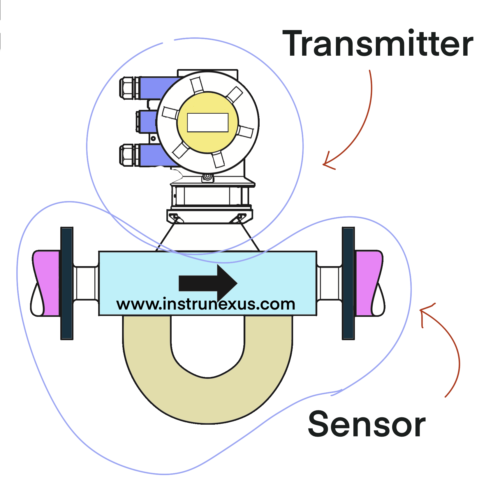
Sensor: This is the primary element in direct contact with the process fluid. It consists of the flow tube(s) through which the fluid passes, the electromechanical driver (exciter) that initiates oscillation, the pickoff sensors that detect the tube’s motion, and a robust outer housing that protects the internal components and provides process containment.
Transmitter: This is the secondary element, or the “brain” of the system. It houses the sophisticated electronics that power the sensor’s drive coil, receive the raw signals from the pickoff sensors (phase shift for mass flow, frequency for density) and the RTD (for temperature), and perform the necessary calculations. The transmitter then converts these measurements into standardized outputs for process control systems, such as 4-20mA analog signals, pulse/frequency outputs, or digital communication protocols like HART, Modbus, or Profibus.
The materials used for the wetted parts—the flow tubes themselves—are of paramount importance. The standard material is typically 316L Stainless Steel, which is suitable for a wide range of applications. However, for highly corrosive chemicals, high-temperature processes, or applications where specific material compatibility is required, manufacturers offer a range of exotic alloys. These include Nickel alloys like Hastelloy C22 (also referred to as Alloy 22) and, for the most aggressive services, materials like Tantalum. Material selection is a critical step because the flow tubes are constructed with very thin walls (often around 1.5 mm) to maximize sensitivity, leaving virtually no allowance for corrosion.
Flow Tube Geometry: A Comparative Analysis
The geometry of the flow tubes is the most significant design differentiator among Coriolis meters. Each shape offers a unique balance of performance and practical considerations, making the choice of geometry highly dependent on the specific application’s priorities.
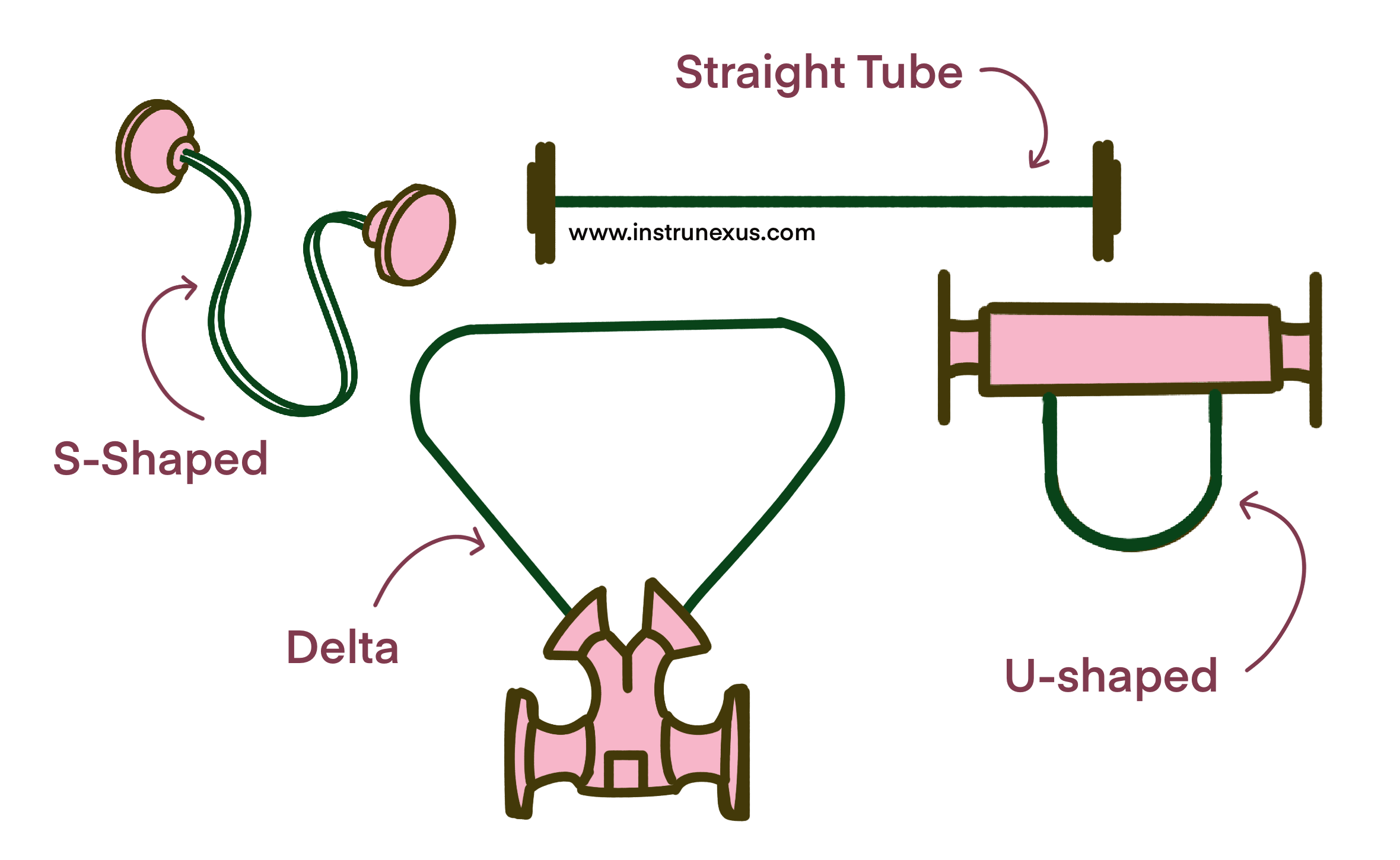
Bent-Tube Designs (U-Tube, S-Shape, Delta): This category represents the original and still most prevalent Coriolis meter design. The curved or bent geometry allows the tubes to be more flexible and displace more easily under the influence of Coriolis forces. This greater movement results in a larger, more distinct phase shift for a given mass flow rate. This characteristic, known as high “flow sensitivity,” is the source of the bent-tube design’s primary advantages: superior accuracy (especially at very low flow rates), excellent repeatability, and a very high turndown ratio. However, these performance benefits come with practical drawbacks. The bends in the flow path create a more tortuous route for the fluid, leading to a higher pressure drop compared to a straight pipe. Furthermore, the curves can make the meter difficult to clean completely and can create low points where liquids, solids, or gases can become trapped, making them less suitable for certain hygienic or slurry applications.
Straight-Tube Designs: Developed to address the limitations of bent-tube meters, straight-tube designs have become the preferred choice for specific demanding applications. As the name implies, the flow passes through one or more straight tubes, offering a completely unobstructed path. This results in a very low pressure drop, which is critical for preventing flashing in volatile liquids or for handling high-viscosity fluids. Their simple geometry also makes them exceptionally easy to clean and fully drainable, a non-negotiable requirement in sanitary processes found in the food, beverage, and pharmaceutical industries. The trade-off for these practical advantages is performance. The inherent rigidity of a straight tube makes it less responsive to Coriolis forces, resulting in a smaller phase shift signal. This lower sensitivity can lead to reduced accuracy and a lower turndown ratio compared to bent-tube designs.
Other Geometries (Micro-bend, Triangular): Recognizing the distinct advantages and disadvantages of the two primary designs, manufacturers have developed compact or hybrid geometries. Designs like the “micro-bend” or “triangular” shape offer a compromise, featuring tubes with a much smaller radius of curvature than traditional U-tubes. These designs aim to reduce the pressure drop and physical footprint associated with bent-tube meters while retaining better sensitivity and accuracy than a purely straight-tube design, making them well-suited for low-flow applications or installations with significant space constraints.
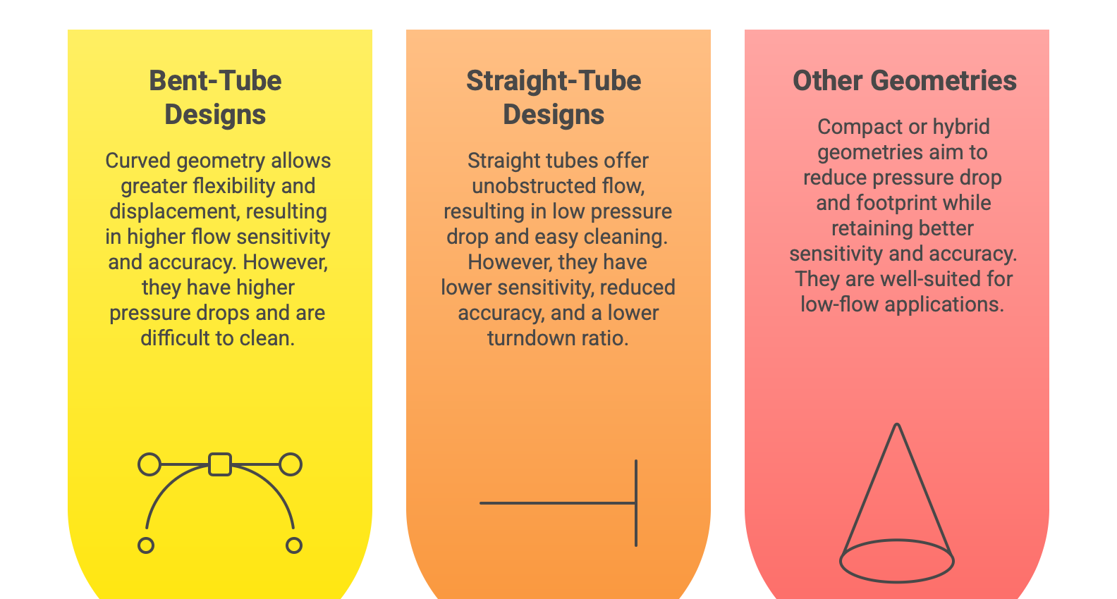
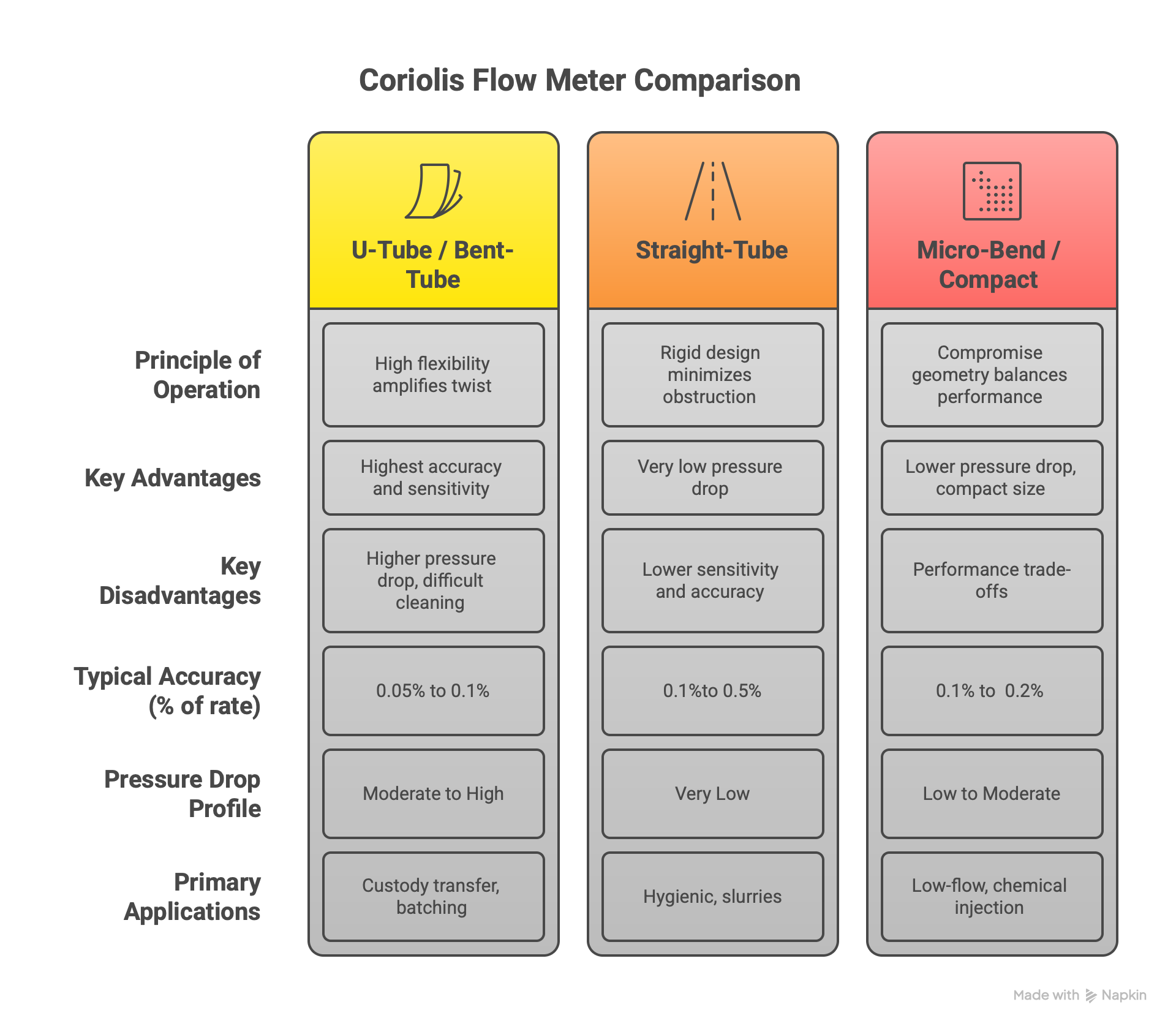
Table 1: Comparative Analysis of Coriolis Flow Tube Geometries
Sensor Configuration: Single vs. Dual-Tube Systems
In addition to geometry, the number of flow tubes used in the sensor design has a significant impact on performance, particularly concerning the meter’s resilience to external factors.
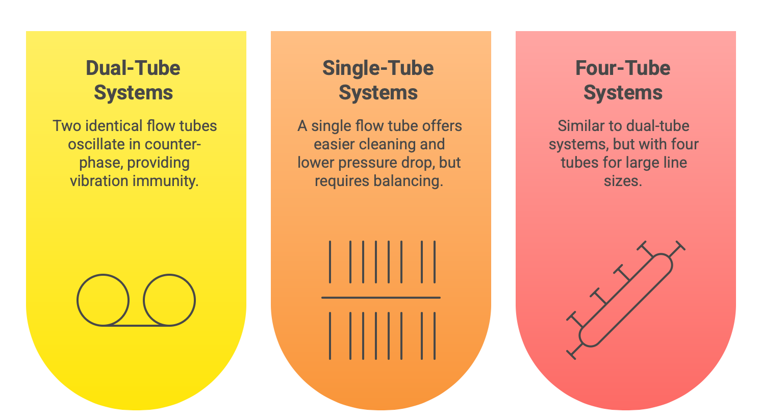
Dual-Tube Systems: This is the most widely used configuration in the industry. The design features two identical flow tubes, typically arranged in parallel. The drive coil excites these tubes to oscillate in opposition to each other, or in “counter-phase”. This balanced, opposing motion is a key feature. Because the tubes are moving against each other, the sensor assembly as a whole remains stable and balanced. This design provides inherent immunity to external plant and pipeline vibrations, as these external forces tend to affect both tubes equally and are canceled out. This decoupling from the surrounding environment leads to a more stable and reliable measurement, especially in challenging industrial settings.
Single-Tube Systems: As the name suggests, these meters utilize a single flow tube. This configuration offers distinct advantages, primarily related to fluid handling. With no flow splitter dividing the stream between two paths, single-tube meters are easier to clean, experience a significantly lower pressure drop, and impose less shear stress on the fluid. These characteristics make them an excellent choice for hygienic applications or for measuring sensitive or viscous fluids. The primary challenge of the single-tube design is its lack of inherent vibration immunity. To overcome this, manufacturers employ sophisticated balancing systems, such as an eccentrically mounted, counter-oscillating pendulum mass, to create a torsional balance that decouples the measurement from external vibrations.
Four-Tube Systems: A less common design, typically reserved for very large line sizes and high flow rate applications, such as pipeline or loading operations. Similar to dual-tube systems, four-tube meters use counter-phase oscillation to achieve the mechanical balance and vibration decoupling necessary for stable measurement.
The variety in Coriolis meter construction demonstrates that there is no universal “best” design. Each configuration represents a calculated engineering decision, balancing the pursuit of maximum performance against the demands of practical application. The goal of measurement is to maximize the desired signal (the phase shift caused by mass flow) while minimizing the influence of noise (external vibration, pressure effects). A bent-tube geometry is an effective way to mechanically amplify the phase-shift signal, which directly enhances accuracy and low-flow sensitivity. However, this amplification comes at the cost of practical issues like higher pressure drop and poor drainability. Conversely, a straight-tube design prioritizes solving these practical problems, providing a low-pressure-drop, easily cleaned flow path, but does so by sacrificing some of the signal amplification, resulting in lower sensitivity. Therefore, the process of selecting a meter’s physical design becomes a direct mapping of the application’s highest priorities. For the fiscal transfer of a clean, valuable liquid where measurement accuracy is the overriding concern, a dual bent-tube meter is the superior choice. For a sanitary pharmaceutical filling line where absolute drainability, cleanability, and low fluid shear are non-negotiable, a single straight-tube meter is often the only viable option.
Selection Criteria for Optimal Performance
Specifying a Coriolis mass flow meter is a multi-faceted engineering task that goes far beyond simply matching the line size. A successful selection requires a thorough understanding of the process conditions, a careful evaluation of performance trade-offs, and a clear definition of the required outputs and certifications. The process is best viewed as a multi-variable optimization problem, where decisions made to enhance one parameter can directly impact another. A systematic approach is essential to ensure the selected instrument delivers the accuracy and reliability expected of the technology.
Defining the Process Environment: The Data Checklist
The foundation of a successful selection is a complete and accurate definition of the process. Before engaging with manufacturers or consulting product data sheets, it is imperative to gather a comprehensive set of data that describes the fluid, the operating conditions, and the physical installation constraints. Incomplete or inaccurate data is a leading cause of mis-specified instrumentation, which can lead to poor performance, process downtime, and financial loss. The following checklist, formalized in Table 2, outlines the critical information required.
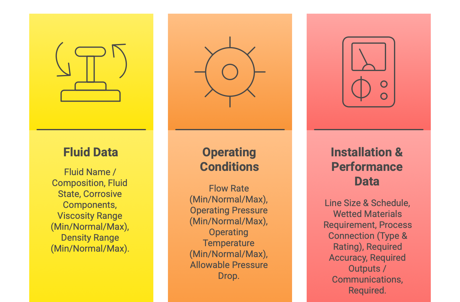
Fluid Properties: A detailed characterization of the medium is essential. This includes its type (liquid, gas, or slurry), its state (e.g., potential for two-phase flow), and its chemical composition. The composition is critical for determining material compatibility and assessing corrosiveness. The expected range of fluid viscosity and density must also be provided, as these properties influence pressure drop calculations and meter performance.
Operating Conditions: The meter must be specified to handle the full range of process dynamics. This requires defining the minimum, normal, and maximum values for the mass or volumetric flow rate, the operating pressure, and the operating temperature.
Piping and Installation: The physical constraints of the installation must be known. This includes the process line size, the required type of process connection (e.g., ANSI flanges, sanitary tri-clamps), and any limitations on available space or meter orientation.
Table 2: Process Data Checklist for Coriolis Meter Selection
Sizing the Meter: The Critical Trade-off
A common misconception is that a Coriolis meter should be the same size as the pipe it is installed in. In reality, Coriolis meters are sized based on the process flow rate, and it is common for the selected meter to be one nominal size smaller than the pipeline. This decision involves a critical trade-off between measurement accuracy and pressure drop.
For a given flow rate, selecting a smaller diameter meter forces the fluid to travel at a higher velocity. This can be advantageous, as it often leads to a stronger Coriolis effect, potentially improving measurement accuracy and the meter’s effective turndown ratio. However, the consequence of this higher velocity is a significantly increased pressure drop across the meter.
In many applications, this pressure drop is a manageable consequence. However, when measuring volatile liquids—such as light hydrocarbons or liquefied gases that are close to their vapor pressure—minimizing pressure drop becomes the paramount concern. An excessive pressure drop can cause the local pressure inside the meter to fall below the fluid’s vapor pressure, leading to the formation of gas bubbles, a phenomenon known as flashing. This creation of a two-phase flow condition within the meter can cause severe measurement errors and, in some cases, cause the meter to stop reading entirely. In these critical applications, the engineer must prioritize the avoidance of flashing. This often means selecting a larger meter than would otherwise be chosen, deliberately sacrificing some low-flow accuracy to ensure the pressure drop remains minimal and the fluid stays in a single liquid phase.
Furthermore, it is essential to size the meter based on the instantaneous flow rate it will experience, not the time-averaged production rate. In applications like well testing or batch processing, flow may be intermittent and occur at very high rates for short periods. The meter must be sized to handle these peak rates accurately and without exceeding pressure drop or velocity limits.
Performance and Communication Specifications
Once the appropriate size and materials are determined, the required performance level and integration capabilities must be specified.
Accuracy: Coriolis meter accuracy is typically specified as a combination of a percentage of the reading and a fixed zero-stability value (e.g., 0.1% of flow rate zero stability). The percentage of rate error is dominant at higher flow rates, while the zero-stability error becomes the primary contributor to total error at very low flow rates. This zero stability effectively defines the lower limit of the meter’s useful measurement range and its turndown.
Turndown Ratio: Also known as rangeability, this is the ratio of the maximum flow rate to the minimum flow rate at which the meter can operate while maintaining its specified accuracy. Coriolis meters are renowned for their exceptionally high turndown ratios, often 100:1 or even higher, allowing them to measure a very wide range of flows with a single device.
Communications and Outputs: The transmitter must be selected to provide the necessary signals for the plant’s control and monitoring systems. This includes traditional analog outputs (4-20mA), discrete pulse or frequency outputs for totalization, and digital communication protocols (e.g., HART, Modbus, Profibus, EtherNet/IP) that provide access to all the meter’s variables and advanced diagnostic information.
Environmental and Safety Considerations
Finally, the meter must be suitable for the environment in which it will be installed.
Hazardous Area Approvals: For installations in environments where flammable gases or dusts may be present, the meter must carry the appropriate hazardous area certifications, such as ATEX in Europe or cCSAus in North America.
Hygienic Certifications: For applications in the food, beverage, and pharmaceutical industries, meters must meet stringent sanitary design standards to prevent contamination and ensure cleanability. Common certifications include 3-A Sanitary Standards and EHEDG (European Hygienic Engineering & Design Group).
Vibration: In areas with significant ambient vibration from pumps, motors, or other equipment, a meter design with high inherent immunity, such as a dual-tube configuration, is strongly recommended to ensure measurement stability.
The selection process for a Coriolis meter clearly demonstrates that a purely theoretical or single-parameter approach is fraught with risk. The interaction between the meter’s characteristics and the fluid’s properties must be the central consideration. The complexity of these interacting variables underscores the necessity of utilizing manufacturer-provided sizing software and engaging in close collaboration with application experts. These resources provide access to empirical performance data and deep application knowledge, which are essential for validating the selection and ensuring the chosen instrument will perform optimally in the real world.
A Survey of Industrial Applications
The unique combination of direct mass flow measurement, high accuracy, and multivariable capability has established the Coriolis meter as a versatile and often indispensable instrument across a vast spectrum of industries. Its applicability stems directly from its foundational principles: direct mass measurement is ideal for transactions and chemical reactions; multivariable density measurement enables advanced process control; and a crevice-free, all-metal construction allows for adaptation to the most stringent hygienic requirements. The following examples illustrate how these core capabilities are leveraged to solve specific challenges in diverse industrial settings.
High-Stakes Measurement: Custody Transfer and Fiscal Metering
In custody transfer applications, the flow measurement serves as the basis for a financial transaction—the “cash register” of the process. This includes the sale of crude oil, natural gas, and refined petroleum products between parties. In these scenarios, accuracy and reliability are paramount to ensure fairness and prevent financial disputes.
The Coriolis meter is exceptionally well-suited for these applications. Its ability to measure mass directly eliminates the ambiguities and potential errors associated with converting volume to mass using separate temperature, pressure, and density measurements. This is particularly crucial when dealing with fluids like crude oil, whose density and composition can vary significantly. The meter’s high accuracy, typically 0.1% of reading or better, meets the stringent requirements of regulatory bodies and industry standards, such as the American Gas Association’s (AGA) Report Number 11 for the custody transfer of natural gas.
Precision Control in Chemical and Petrochemical Processing
Chemical reactions are governed by stoichiometry, which is based on the mass of the reactants, not their volume. The Coriolis meter’s direct mass measurement capability makes it the ideal instrument for applications requiring precise ratio control, dosing, and blending to ensure optimal reaction, high product quality, and maximum yield.
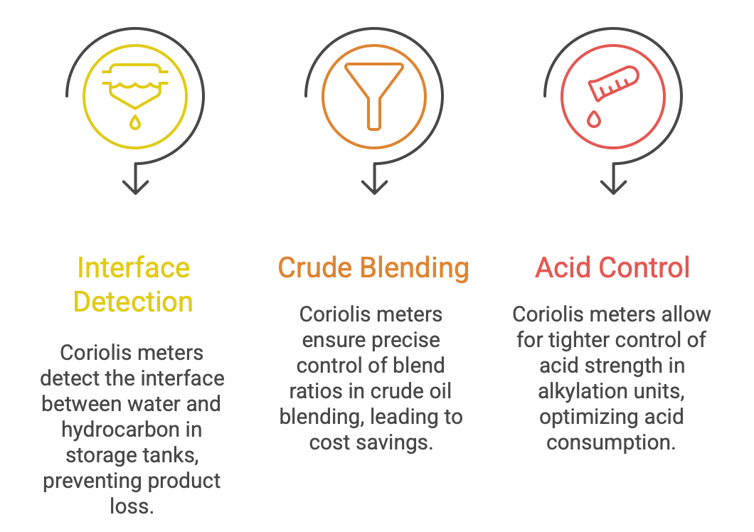
Interface Detection in Tank Dewatering: In refineries, storage tanks for hydrocarbons often accumulate water that must be drained periodically. Traditional methods risk discharging valuable hydrocarbon along with the water. A Coriolis meter installed on the drain line can use its real-time density measurement to precisely detect the interface between the denser water and the lighter hydrocarbon. This density signal can be used to automatically close the drain valve at the exact moment the interface is detected, preventing product loss and ensuring compliance with environmental regulations.
Crude Blending: Refineries often blend various crude oil stocks to create an optimal feedstock for their processing units. Because the properties of these crudes vary, volumetric meters can introduce significant errors. Coriolis meters provide an accurate mass-based measurement that is unaffected by these variations, enabling precise control of blend ratios. This allows refiners to take advantage of price differentials between different crudes while maintaining a consistent feedstock quality, leading to significant cost savings and improved downstream processing.
Acid Control in Alkylation Units: In sulfuric acid alkylation units, the strength (concentration) of the acid is a critical process parameter. The density of the acid solution is directly correlated to its concentration. By measuring the density online, a Coriolis meter allows for tighter control of the acid strength, which helps to optimize the consumption of fresh acid and reduce operating costs.
Hygienic Applications in Food, Beverage, and Pharmaceuticals
Processes in the food, beverage, and pharmaceutical industries demand the highest levels of precision, repeatability, and, above all, cleanliness to ensure product safety and consistency.
Coriolis meters, particularly straight-tube designs, are engineered to meet these demands. Their smooth, crevice-free flow path, constructed from polished stainless steel or other compatible alloys, offers excellent drainability and is easily cleaned and sterilized in-place (CIP/SIP). This design complies with stringent hygienic standards like ASME BPE and 3-A. Furthermore, their ability to accurately measure highly viscous or non-Newtonian fluids like syrups, chocolate, creams, and yogurts is a significant advantage over other technologies.
Food & Beverage: Coriolis meters are used for precise batching and blending of ingredients, such as dosing high-fructose corn syrup into soft drinks, measuring milk fat content to ensure dairy product consistency, monitoring pasteurization flow rates, and managing high-accuracy filling operations to minimize product give-away. Their density measurement can also be used to monitor quality parameters like the Brix (sugar content) of fruit juices or the Plato scale in brewing.
Pharmaceuticals: In pharmaceutical manufacturing, reproducibility is critical. Coriolis meters provide the high-accuracy, repeatable measurement needed for dosing active pharmaceutical ingredients (APIs), feeding nutrients into bioreactors, applying precise pill coatings, and performing high-value filling of vials and syringes. Their independence from fluid properties like conductivity and viscosity makes them more reliable than alternatives for these critical downstream processes.
Handling Challenging Fluids and Process Conditions
The robust design and unique measurement principle of the Coriolis meter make it suitable for applications that are difficult or impossible for other flow technologies.
Slurries and Viscous Fluids: Because the measurement is based on mass and inertia, it is largely unaffected by changes in fluid viscosity. The absence of moving parts or internal obstructions (especially in straight-tube designs) means there is nothing to wear out, clog, or be damaged by abrasive slurries.
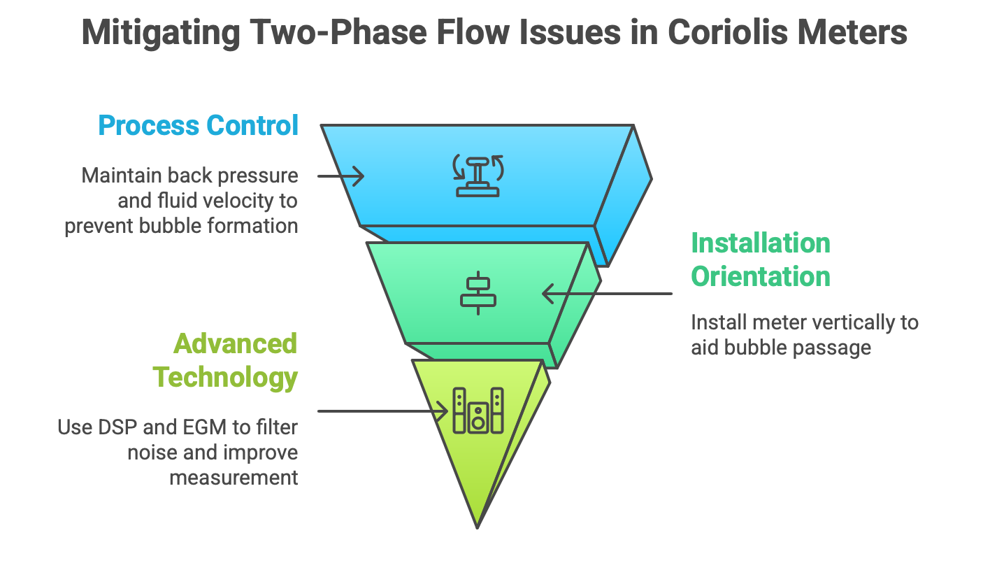
Two-Phase (Gas-Liquid) Flow: The presence of entrained gas or bubbles in a liquid stream is one of the most significant challenges for a Coriolis meter. The gas bubbles dramatically increase the damping of the fluid, which requires more energy to maintain the tube’s oscillation. This can exceed the power limits of the meter’s drive system, causing the vibration amplitude to decrease significantly or “stall”. This condition leads to a poor signal-to-noise ratio and large measurement errors. Several strategies are employed to mitigate this issue:
Process Control: Ensuring sufficient back pressure on the meter to keep gases dissolved and maintaining a high enough fluid velocity (typically above 1 m/s or 20% of the meter’s nominal range) helps to sweep bubbles through the meter before they can coalesce and cause problems.
Installation Orientation: Installing the meter in a vertical pipe with the flow direction upwards is the preferred orientation. This uses buoyancy to help any bubbles pass through the meter rather than becoming trapped in the upper bends of the tubes.
Advanced Technology: Modern Coriolis transmitters are equipped with high-speed Digital Signal Processing (DSP). These advanced electronics can apply sophisticated filtering algorithms to the noisy signal generated during two-phase flow conditions. This allows the transmitter to extract a stable and more reliable mass flow measurement even when the tube’s vibration amplitude is reduced, significantly improving performance in aerated applications. Some manufacturers offer specialized software, sometimes called Entrained Gas Management (EGM), specifically for this purpose.
The diverse range of applications demonstrates that the Coriolis meter is more than a simple measurement device; it is a platform technology. Its core capabilities can be leveraged in innovative ways to solve complex process challenges. The value of the instrument often extends far beyond flow totalization, providing the critical real-time data needed to enable new levels of process automation, quality control, and operational optimization.
Installation, Calibration, and Maintenance Best Practices
The exceptional performance of a Coriolis mass flow meter is not solely a product of its sophisticated design; it is critically dependent on correct installation, proper commissioning procedures, and diligent maintenance. While the technology is robust and requires minimal routine intervention, adherence to best practices during its operational lifecycle is essential to realize and sustain its specified accuracy and reliability. A failure in procedure can easily negate the benefits of a high-precision instrument.
Installation and Orientation
Proper mechanical installation is the first step toward reliable measurement. It focuses on ensuring the meter is correctly oriented for the process fluid and is not subjected to external stresses that could compromise its performance.
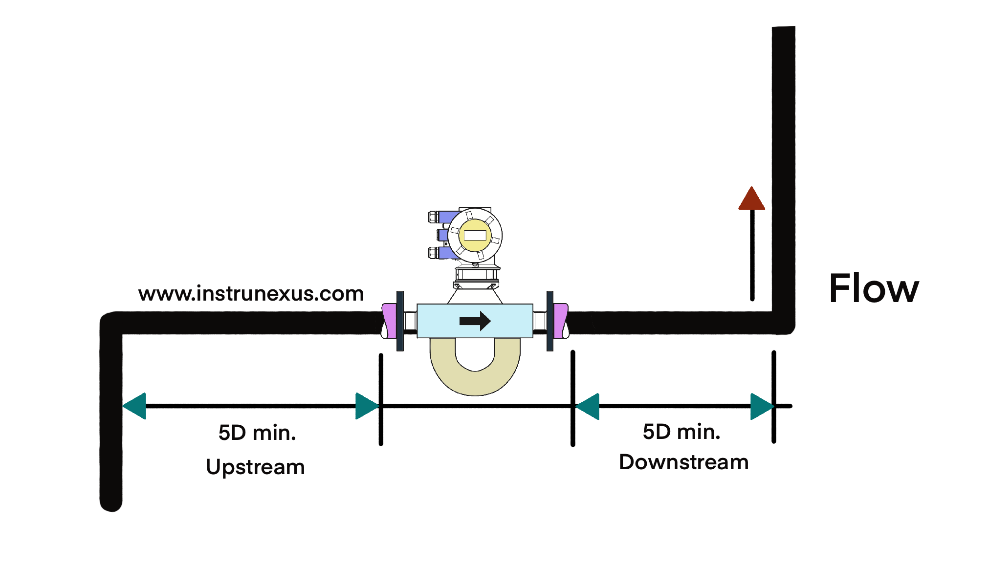
Piping Requirements: A significant advantage of the Coriolis meter is its inherent immunity to flow profile distortions and swirl. Unlike many other technologies that require long, straight runs of pipe upstream and downstream to condition the flow, Coriolis meters generally have no such requirement. This allows for much greater flexibility in installation, especially in compact or retrofit applications. However, some expert bodies, such as the National Engineering Laboratory (NEL), recommend following good piping practice by installing a minimum of 5 pipe diameters (5D) of straight pipe upstream and downstream. This is not for flow conditioning but to ensure a stable mechanical installation and provide adequate space to clamp the adjoining pipework securely, thereby minimizing the transmission of stress to the meter.
Orientation: The physical orientation of the meter in the pipeline is critical, particularly when dealing with fluids that are not perfectly homogeneous, such as liquids with potential for entrained gas or slurries with solids that could settle.
Preferred Orientation: The universally preferred installation is in a vertical pipe with the flow direction moving upwards. This orientation ensures that the meter tubes remain completely full of liquid under all flow conditions. Crucially, it uses the force of buoyancy to help sweep any entrained gas bubbles up and out of the meter, preventing them from becoming trapped.
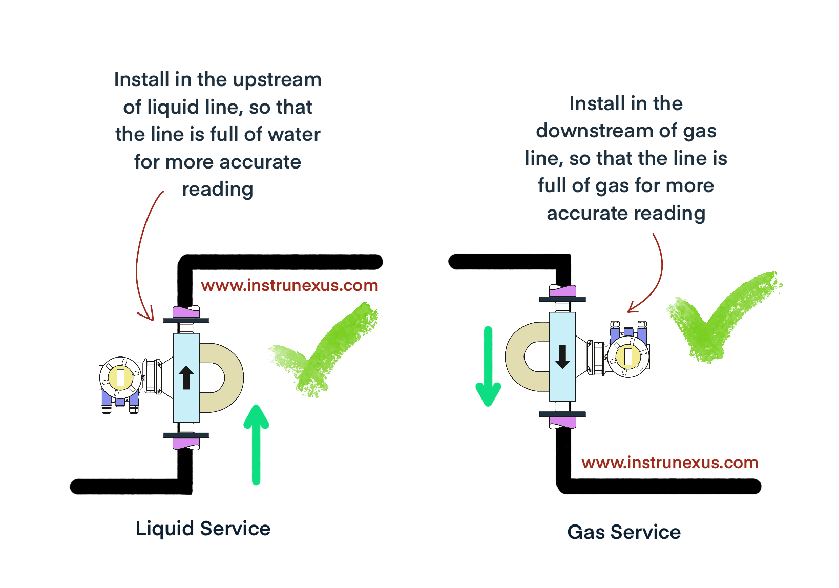
Acceptable Orientation: Horizontal installation is also acceptable but requires careful consideration of the tube geometry. The meter should be positioned like the bottom of a “U” in the pipeline, ensuring it remains flooded and acts as a low point to prevent draining. The orientation of the tubes themselves should be such that they do not create a high point where air can be trapped or a low point where solids can settle.

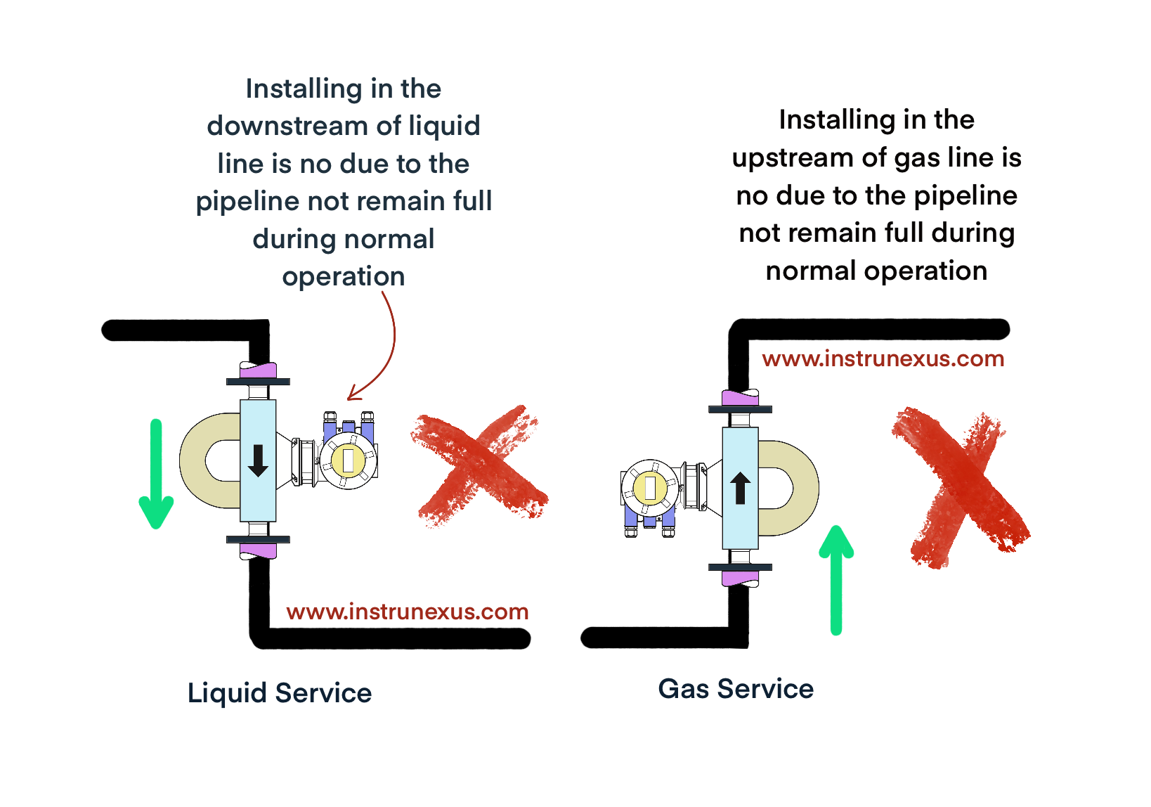
Not Recommended: Installation in a vertical pipe with downward flow is strongly discouraged. This configuration makes it very difficult to ensure the tubes remain full, especially at low flow rates, and can easily lead to air entrapment and inaccurate measurement.
Mechanical Installation: The meter must be installed in a manner that does not introduce external stress into the sensor housing. Misaligned pipes that have to be forced into place can exert significant bending or torsional forces on the meter. These stresses can distort the delicate balance of the oscillating tubes, creating a bias in the measurement and affecting the meter’s zero point and overall accuracy. Standard piping supports should be installed on the pipeline on both sides of the meter to support its weight and isolate it from pipe strain.
The Critical Zeroing Procedure
Performing a meter zero after installation is arguably the single most important commissioning step to ensure accurate field performance. The meter’s factory-calibrated zero point can be influenced by the unique conditions of its final installation, including mounting stresses, process pressure, and operating temperature. A field zero procedure measures and compensates for these installed-state biases, establishing a true and accurate baseline for measurement.
The procedure for performing a meter zero is as follows:
The meter must be completely filled with the actual process fluid. The fluid should be circulated for a period to allow the meter’s temperature and pressure to stabilize at normal operating conditions.
A true zero-flow condition must be established. This is achieved by closing a tight-shutoff valve (a double-seated or double block-and-bleed valve is preferred). The valve should ideally be located downstream of the meter to maintain operating pressure within the sensor.
Once the flow is stopped and the process is stable, the zeroing function is initiated through the meter’s transmitter interface or associated software.
After the zeroing is complete, the new zero value should be verified to ensure it is stable and within the manufacturer’s specified tolerance. It is good practice to perform this check periodically (e.g., quarterly during the first year of service) to monitor for any drift.
Calibration, Verification, and Proving
Factory Calibration: Every Coriolis meter undergoes a primary calibration at the factory before shipment. This is typically performed using a gravimetric method, where the mass of a fluid passed through the meter is precisely weighed over a measured time period. This process determines the meter’s unique Flow Calibration Factor (FCF), which is the constant that relates the measured phase shift (Delta t) to the mass flow rate. This calibration is traceable to national and international standards (e.g., ISO 17025).
Field Verification: Modern smart transmitters are equipped with advanced diagnostic tools that allow for in-situ verification of the meter’s health and calibration. These tools can monitor the structural integrity of the flow tubes by analyzing their vibrational characteristics. This is not a recalibration; rather, it is a powerful diagnostic test that can confirm that the meter’s original FCF is still valid, providing a high degree of confidence in the measurement without removing the meter from the process line.
Proving: In high-accuracy applications like custody transfer, the meter’s performance is periodically validated in the field using a process called proving. This involves diverting the flow through a portable or permanently installed calibration standard, such as a small volume prover (SVP) or ball prover. The total mass or volume registered by the Coriolis meter is compared against the known volume of the prover. The result of this comparison is used to generate a “Meter Factor,” a correction coefficient close to 1.0000 that fine-tunes the meter’s output to align perfectly with the prover under actual operating conditions.
Routine Maintenance and Troubleshooting
One of the major advantages of Coriolis meters is their minimal maintenance requirement, stemming from their all-welded, no-moving-parts design.
Routine Maintenance: There are no bearings to lubricate or blades to replace. Routine maintenance primarily consists of periodic zero checks, visual inspection of the housing and wiring connections for integrity and sealing, and ensuring the meter remains clean, especially in applications where fluid fouling or coating is a possibility.
Troubleshooting Common Issues:
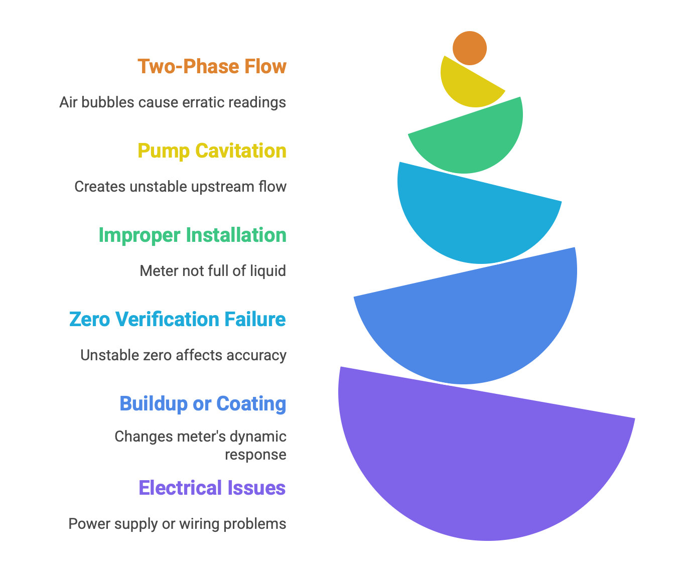
Fluctuating or Erratic Readings: This is most commonly caused by two-phase flow (air or gas bubbles in a liquid). Other causes can include pump cavitation upstream of the meter or installation in a location where the meter is not kept full of liquid.
Inaccurate or Drifting Readings: The first step is always to perform a meter zero verification under proper conditions. If the zero is stable, the issue could be due to a buildup or coating on the inside of the tubes, which changes the meter’s dynamic response. Advanced diagnostics, such as monitoring the “drive gain” (the amount of power required to vibrate the tubes), can help identify such conditions; an increase in drive gain often points to coating or aeration.
No Reading: This is typically an electrical issue. The first steps are to check the power supply to the transmitter and the integrity of the wiring connections between the transmitter and the sensor.
The lifecycle management of a Coriolis meter reveals a crucial relationship between the instrument and its operating environment. While the device itself is highly sophisticated, its sustained accuracy is not guaranteed by its design alone. It depends critically on the procedural correctness of the engineer who installs and commissions it. An error as simple as neglecting to perform a field zero after installation can introduce a fixed offset that completely invalidates the meter’s high specified accuracy, especially at lower flow rates. This highlights a shift in focus from traditional mechanical maintenance to a more holistic approach that emphasizes understanding the interaction between the meter and the process, and the importance of correct operational procedures.
Comparative Analysis and Future Trends
The Coriolis mass flow meter, while a powerful and versatile technology, is one of many solutions available for fluid measurement. Its selection must be justified by a clear understanding of its capabilities relative to other technologies, considering factors such as performance, fluid compatibility, installation constraints, and total cost of ownership. Furthermore, the technology is not static; ongoing advancements in electronics, software, and sensor design are continuously expanding its capabilities and addressing its traditional limitations, positioning it as a key component in the future of process automation.
Coriolis Meters vs. Alternative Technologies
A comparative analysis places the Coriolis meter’s strengths and weaknesses in context, guiding an engineer toward the most appropriate technology for a given application.
vs. Ultrasonic Flow Meters: Ultrasonic meters measure fluid velocity by analyzing the transit time of sound pulses across a pipe. Their key advantage is their non-invasive nature, with clamp-on models that can be installed without cutting the pipe or shutting down the process. They excel in very large line sizes where a Coriolis meter would be prohibitively large and expensive, and they have virtually no pressure drop. For these reasons, they are a preferred technology for the custody transfer of natural gas in large transmission pipelines. The Coriolis meter, in contrast, offers fundamentally higher accuracy, measures mass directly, and is unaffected by changes in the fluid’s acoustic properties.
vs. Magnetic Flow Meters: Magnetic meters operate on Faraday’s Law, measuring the voltage induced by a conductive fluid flowing through a magnetic field. Their primary strengths are their significantly lower cost compared to Coriolis meters and their low-pressure-drop, obstruction-less design. They are an excellent and cost-effective choice for measuring water-based or other conductive liquids. Their critical limitation is that they cannot measure non-conductive fluids, such as hydrocarbons, oils, and pure solvents, nor can they measure gases. The Coriolis meter overcomes this limitation entirely and also provides a direct mass and density measurement, which the magnetic meter cannot.
vs. Differential Pressure (DP) Meters: This category, including orifice plates, venturis, and advanced cones like the V-Cone, is one of the oldest and most widely used flow measurement technologies. DP meters infer flow rate from the pressure drop created by an obstruction in the flow path. They are simple, robust, relatively low-cost, and can be used in extremely high-temperature and high-pressure applications. However, they have significantly lower accuracy and turndown compared to Coriolis meters, suffer from wear that degrades accuracy over time, and require long straight pipe runs for proper flow conditioning. Most importantly, they measure velocity to infer volume, and require separate pressure and temperature measurements to calculate mass flow. The Coriolis meter’s superior accuracy, high turndown, and direct mass measurement often justify its higher initial cost in critical applications.
Table 3: Comparison of Major Flow Meter Technologies
This comparative framework is essential for the selection process. For an engineer tasked with measuring a non-conductive hydrocarbon for custody transfer, the table provides a clear rationale. A magnetic meter is immediately ruled out due to fluid incompatibility. A DP meter lacks the required accuracy. An ultrasonic meter is a possibility, but the Coriolis meter offers superior accuracy and direct mass measurement. The table thus allows for an evidence-based process of elimination, justifying the selection of the more expensive but technically superior Coriolis meter to meet the non-negotiable requirements of the application.
Technological Advancements and Outlook
The Coriolis meter is a technology in continuous evolution, driven primarily by advancements in electronics and software that augment the fundamental mechanical sensor.
Digital Signal Processing (DSP): The transition from analog to digital transmitters has been the single most transformative development in modern Coriolis technology. High-speed DSP enables the use of advanced algorithms that can intelligently filter the raw sensor signals. This allows the meter to distinguish the true flow signal from noise caused by external vibration or, critically, from the chaotic signals generated during two-phase flow conditions. This capability has dramatically improved the meter’s performance and reliability in challenging applications that were previously considered unsuitable.
Smart Diagnostics and Verification: Modern transmitters do more than just calculate flow; they continuously monitor the health of the sensor itself. By tracking parameters like “drive gain”—the amount of power needed to maintain the tube’s vibration—the meter can diagnose process problems in real-time. A gradual increase in drive gain might indicate product coating or fouling inside the tubes, while a sudden spike often signals aeration or slug flow. This diagnostic information enables predictive maintenance and allows operators to verify the meter’s health and calibration integrity without interrupting the process.
Miniaturization and New Sensor Designs: There is a clear trend toward developing more compact meters for low-flow applications, such as those found in laboratories, pilot plants, and chemical injection systems. This includes research into alternative sensor technologies, such as those based on Micro-Electro-Mechanical Systems (MEMS), which promise to further shrink the footprint and expand the technology’s reach into new domains.
Enhanced Connectivity (Industry 4.0): The latest generation of transmitters is designed for seamless integration into modern plant architectures. With enhanced communication protocols and IoT capabilities, Coriolis meters can provide a rich stream of real-time data not only to the control system but also to plant-wide asset management, process optimization, and data analytics platforms. This facilitates remote diagnostics, improved data historian capabilities, and a more holistic view of process health.
These advancements signal a clear trajectory for the technology. The Coriolis meter is evolving from a standalone instrument into an intelligent, multi-faceted process sensor. Its value is increasingly defined not just by the primary measurement it provides, but by the wealth of actionable insights it can offer about the process itself. It can report not only how much fluid is flowing, but also provide crucial information about what is flowing (via density and concentration) and how well the process is running (via advanced diagnostics). This positions the Coriolis meter as a cornerstone technology for data-driven process automation and optimization in the era of Industry 4.0.
Conclusion
The Coriolis mass flow meter stands as a testament to the successful application of a fundamental physical principle to solve a complex industrial challenge. Its ability to measure mass flow directly, independent of the physical properties of the fluid, fundamentally distinguishes it from all other flow measurement technologies. This core capability is the source of its unparalleled accuracy, repeatability, and versatility, making it an indispensable tool in applications where precision and reliability are paramount, from fiscal custody transfer to the formulation of life-saving pharmaceuticals.
The analysis of its design variants reveals a landscape of deliberate engineering trade-offs. The choice between a high-sensitivity bent-tube design and a low-pressure-drop, easily cleaned straight-tube design is not a matter of one being superior to the other, but of meticulously matching the instrument’s characteristics to the highest priorities of the specific application. This highlights the critical role of the instrumentation engineer in conducting a thorough evaluation of process conditions to ensure a successful specification.
Furthermore, the operational lifecycle of the meter underscores that sustained accuracy is a shared responsibility between the instrument and its user. The most sophisticated meter can be rendered inaccurate by improper installation or the omission of the critical field zeroing procedure. This shifts the focus from purely mechanical maintenance to procedural correctness and a deeper understanding of the meter’s interaction with the process.
Finally, the technology is far from static. The relentless advancement of digital signal processing, smart diagnostics, and enhanced connectivity is continually pushing the boundaries of what is possible. These innovations are transforming the Coriolis meter from a simple measurement device into an intelligent process sensor, capable of providing a rich, multi-faceted stream of data that enables new levels of process control, automation, and optimization. As industries continue to demand greater efficiency, quality, and insight into their operations, the Coriolis mass flow meter is poised to play an increasingly central role as a key enabling technology.