Differential Pressure Transmitters: A Comprehensive Guide to Principles and Use Cases
In the intricate world of industrial automation and process control, precision is paramount. For instrumentation professionals and students alike, understanding the tools that enable this precision is fundamental. Among the most versatile and widely used of these instruments is the differential pressure transmitter. This comprehensive guide will delve into the core principles of how differential pressure transmitters work, explore their diverse use cases across various industries, and provide insights into their operation, complete with illustrative block diagrams.
What is a Differential Pressure Transmitter?
A differential pressure (DP) transmitter is a device that measures the difference between two pressures. It has two process connections, a ‘high-pressure’ side (HP) and a ‘low-pressure’ side (LP). The transmitter calculates the difference between these two pressures and converts it into a proportional analog or digital electrical signal, typically a 4-20 mA current loop or a digital signal using protocols like HART, FOUNDATION Fieldbus, or Profibus. This output signal can then be used by a control system, such as a PLC (Programmable Logic Controller) or a DCS (Distributed Control System), to monitor and control a process.
The ability to measure a pressure difference rather than an absolute or gauge pressure makes the DP transmitter an incredibly versatile instrument, capable of much more than simple pressure measurement.
The Working Principle: How Do They Do It?
At the heart of every differential pressure transmitter is a sensor that converts the pressure difference into a measurable electrical signal. While various sensor technologies exist, the most common are piezoresistive and capacitive sensors.
A Generic Block Diagram of a Differential Pressure Transmitter
Regardless of the specific sensor technology, the fundamental working principle can be illustrated with a general block diagram:

Block Diagram: General Working Principle of a Differential Pressure Transmitter
Here’s a breakdown of the process:
- Pressure Input: The two pressures to be compared are applied to the high-pressure (HP) and low-pressure (LP) ports of the transmitter.
- Sensing Diaphragms: These pressures are transmitted through isolating diaphragms, which are flexible membranes that protect the internal sensor from the process fluid. An internal fill fluid (typically silicone oil) transfers the pressure from the isolating diaphragms to the central sensing element.
- Sensing Element: This is the core of the transmitter.
- Piezoresistive Sensors: These sensors utilize the piezoresistive effect, where the electrical resistance of a material changes in response to mechanical stress. The pressure difference causes the sensing diaphragm to deflect, creating stress in the embedded piezoresistive strain gauges. This change in resistance is then measured by a Wheatstone bridge circuit.
- Capacitive Sensors: In this design, the sensing diaphragm is positioned between two stationary capacitor plates. The pressure difference causes the diaphragm to move closer to one plate and further from the other, changing the capacitance of the two capacitors. This change in capacitance is then converted into an electrical signal.
- Electronics Module: The raw electrical signal from the sensing element is weak and non-linear. The electronics module conditions, amplifies, and linearizes this signal, converting it into a standard industrial output signal (e.g., 4-20 mA). Modern transmitters also include a microprocessor for advanced diagnostics, self-calibration, and communication capabilities.
- Output Signal: The final, conditioned signal is transmitted to the control system, providing a real-time measurement of the differential pressure.
Key Use Cases of Differential Pressure Transmitters
The versatility of DP transmitters stems from their ability to infer various process variables from a simple pressure difference. Here are some of the most common and critical applications:
1. Flow Measurement
One of the most widespread uses of DP transmitters is for measuring fluid flow in a pipe. This is achieved by introducing a primary element, such as an orifice plate, venturi tube, or flow nozzle, into the pipe. This element creates a restriction, causing the fluid velocity to increase and its pressure to decrease, in accordance with Bernoulli’s principle.
Block Diagram: Flow Measurement using a DP Transmitter and an Orifice Plate
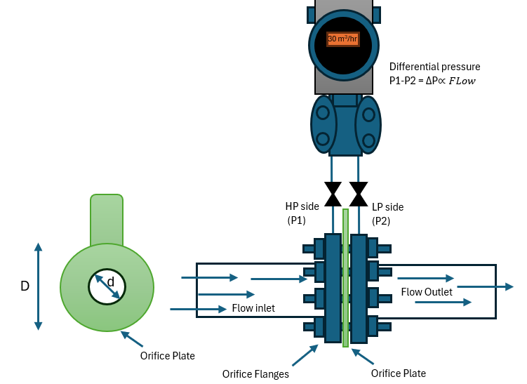
- Principle: The pressure difference measured across the primary element is proportional to the square of the flow rate. The DP transmitter measures this pressure difference, and the control system then calculates the flow rate using a known formula.
- Industry Examples: This method is extensively used in the oil and gas, chemical, power generation, and water treatment industries for monitoring and controlling fluid transfer.
2. Level Measurement
DP transmitters are also a reliable and common solution for measuring the level of liquids in tanks, both open (vented to the atmosphere) and closed (pressurized).
a) Open Tank Level Measurement
In an open tank, the transmitter measures the hydrostatic pressure exerted by the liquid column. The high-pressure side is connected to the bottom of the tank, and the low-pressure side is left open to the atmosphere.
Block Diagram: Open Tank Level Measurement
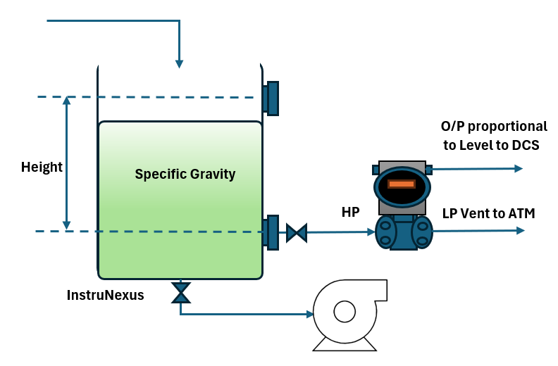
- Principle: The hydrostatic pressure is directly proportional to the height (level) of the liquid and its specific gravity (). Since the specific gravity () and gravity () are known constants, the measured pressure directly indicates the liquid level ().
b) Closed Tank Level Measurement
For pressurized tanks, a second connection is required to compensate for the pressure of the gas or vapor above the liquid (the headspace pressure). The high-pressure side is connected to the bottom of the tank, and the low-pressure side is connected to the top of the tank.
Block Diagram: Closed Tank Level Measurement

- Principle: The DP transmitter measures the difference between the pressure at the bottom (hydrostatic pressure + headspace pressure) and the pressure at the top (headspace pressure). The result is the hydrostatic pressure of the liquid, which is directly proportional to the level.
3. Filter and Strainer Monitoring
Differential pressure is an excellent indicator of the health and performance of filters and strainers in a process line. As the filter clogs with contaminants, the resistance to flow increases, resulting in a larger pressure drop across the filter.
Block Diagram: Filter Monitoring
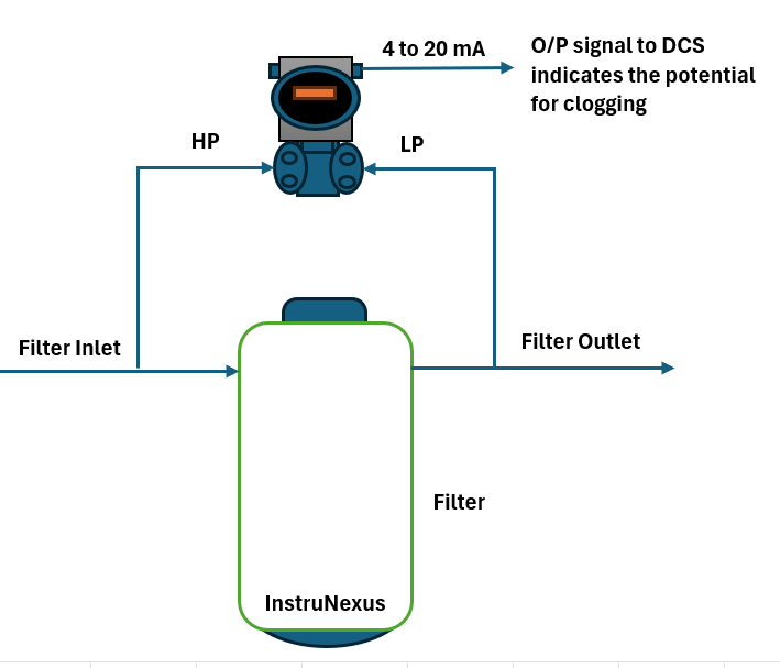
- Principle: By measuring the differential pressure across the filter, operators can monitor its condition in real-time. A rising differential pressure indicates that the filter is becoming clogged and needs to be cleaned or replaced.
- Industry Examples: This is crucial in applications like HVAC systems, hydraulic systems, and water treatment plants to ensure efficient operation and prevent damage to downstream equipment.
4. Density and Interface Measurement
DP transmitters can also be used for more advanced applications like measuring the density of a liquid or detecting the interface between two immiscible liquids with different densities.
- Density Measurement: By using two DP transmitters at a known vertical distance apart in a tank, the density of the liquid can be calculated. The difference in hydrostatic pressure between the two points is directly related to the density of the fluid.
- Interface Measurement: In a vessel containing two immiscible liquids (e.g., oil and water), a DP transmitter can be used to determine the location of the interface. The total hydrostatic pressure measured will be a function of the height and density of both liquids. As the interface level changes, the overall pressure reading will change in a predictable way.
Advantages of Using Differential Pressure Transmitters
- Versatility: As demonstrated, a single type of instrument can be used for a wide range of measurements.
- Accuracy and Reliability: Modern DP transmitters offer high accuracy and are built to withstand harsh industrial environments.
- Proven Technology: The principles behind DP measurement are well-understood and have been proven over decades of use.
- Cost-Effective: For many applications, DP transmitters provide a cost-effective solution compared to other measurement technologies.
- Standardized Outputs: Their standardized output signals make them easy to integrate into existing control systems.
Conclusion:
The differential pressure transmitter, though often hidden from plain sight, is a true workhorse in the world of instrumentation and control. Its ability to accurately measure a simple pressure difference unlocks a wealth of information about a process, enabling engineers and operators to monitor and control flow, level, and other critical variables with confidence. For students entering the field and seasoned professionals alike, a thorough understanding of the principles and diverse applications of DP transmitters is essential for designing, operating, and maintaining efficient and safe industrial processes. The next time you see a complex industrial plant in operation, remember that much of its precise control relies on the humble yet powerful differential pressure transmitter.