Displacer Level Measurement vs. DP and Radar
In the world of industrial process control, accurately measuring the level of liquids and solids in a vessel is paramount. The right level measurement technology can be the difference between a safe, efficient, and profitable operation and one plagued by costly errors, downtime, and safety hazards. Three of the most common and often-debated technologies for continuous level measurement are Displacer, Differential Pressure (DP), and Radar.
This in-depth guide will provide a comprehensive comparison of these three technologies, exploring their working principles, key advantages and disadvantages, and ideal applications. We’ll also provide a framework to help you choose the best-fit technology for your specific needs.
A Quick Primer on Level Measurement
Before we dive into the specifics, let’s establish a foundational understanding. Continuous level measurement, as the name suggests, provides a constant, real-time reading of the level of a substance within a container. This data is crucial for:
Process Control: Maintaining optimal levels for reactions, mixing, or other processes.
Inventory Management: Accurately tracking the quantity of raw materials and finished products.
Safety: Preventing overfills that could lead to spills, environmental damage, and hazardous situations, as well as preventing low-level conditions that could damage equipment like pumps.
The choice of technology to achieve this is critical and depends on a multitude of factors, from the nature of the material being measured to the operating conditions of the vessel.
Displacer Level Measurement: The Veteran
Displacer level transmitters are a traditional and well-established method for level measurement. They operate on a principle that has been a cornerstone of physics for centuries.
Working Principle
The operation of a displacer level transmitter is based on Archimedes’ principle. A displacer, a weighted cylinder, is suspended in the process fluid. As the liquid level rises, the displacer is submerged, and a buoyant force is exerted on it, making it appear lighter. This change in apparent weight is directly proportional to the liquid level. This change is then converted into a 4-20mA signal by a transmitter.
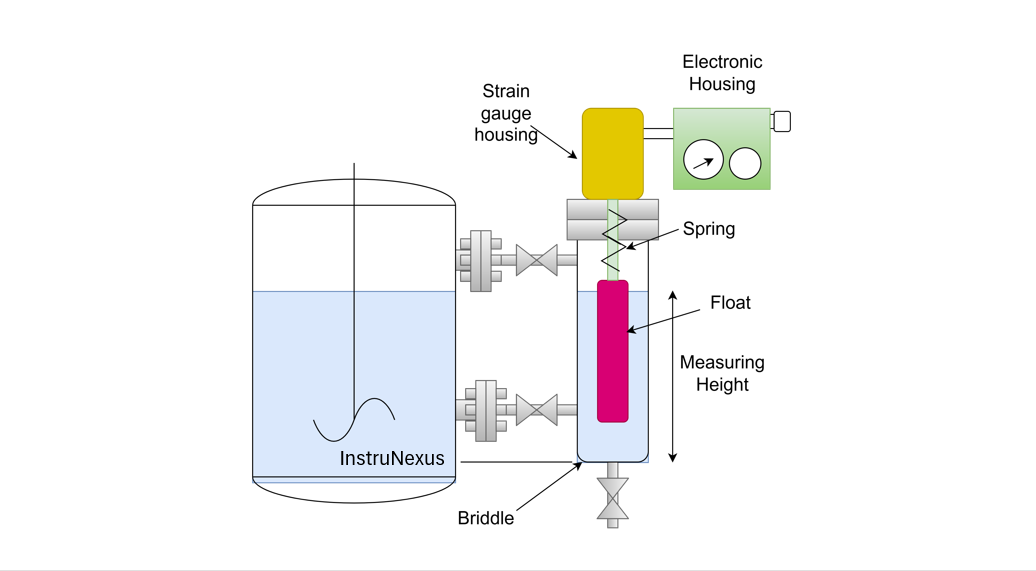
![]()
A simplified block diagram of a Displacer Level Measurement system.
Advantages of Displacer Level Measurement
Reliable and Proven: Having been used for decades, this technology is well-understood and has a long track record of reliability in certain applications.
Good for Clean Liquids: Displacers perform well in applications with clean, non-coating, and non-crystallizing liquids.
Interface Level Measurement: They are one of the few technologies that can effectively measure the interface level between two immiscible liquids with different specific gravities, such as oil and water.
Disadvantages of Displacer Level Measurement
Moving Parts: The mechanical nature of displacers means they have moving parts that are susceptible to wear, plugging, and fouling, leading to higher maintenance requirements.
Density Dependent: The measurement is directly affected by changes in the process fluid’s density. If the specific gravity of the liquid changes, the calibration will be inaccurate.
Limited Span: While they can be used for various tank heights, they become increasingly cumbersome and expensive for longer measurement spans.
Installation and Cost: Installation can be complex, and the overall cost, including the stilling well often required, can be high.
Ideal Applications for Displacer Level Measurement
Clean liquid level measurement in applications with constant density.
Interface level measurement between two clean, immiscible liquids.
High-temperature and high-pressure applications where other technologies might struggle.
Differential Pressure (DP) Level Measurement: The Workhorse
DP level measurement is arguably the most common method for continuous level measurement in the process industries. Its popularity stems from its versatility and cost-effectiveness.
Working Principle
DP level measurement relies on hydrostatic pressure. The pressure exerted by a column of liquid is directly proportional to its height (level) and density. A DP transmitter measures the pressure difference between the high-pressure side (at the bottom of the measurement range) and the low-pressure side (at the top of the measurement range). This differential pressure is then converted into a level reading.
For open (vented) tanks, the low-pressure side is vented to the atmosphere. For closed (pressurized) tanks, the low-pressure side is connected to the vapor space at the top of the tank.

A simplified block diagram of a DP Level Measurement system.
Advantages of DP Level Measurement
Versatile and Widely Used: DP transmitters can be used for a wide range of liquids and applications.
Cost-Effective: The initial purchase price of a DP transmitter is generally lower than that of other technologies.
External Mounting: The transmitter is mounted externally to the vessel, which can simplify installation and maintenance.
High-Pressure and High-Temperature Capability: With appropriate diaphragm seals, DP systems can handle extreme process conditions.
Disadvantages of DP Level Measurement
Density Dependent: Similar to displacers, DP measurement is highly dependent on the density of the process fluid. Any change in density will result in an inaccurate level reading unless compensated for.
Impulse Lines: The use of impulse lines to connect the transmitter to the process can lead to issues like clogging, freezing, and leakage, requiring regular maintenance.
Complex Installation for Closed Tanks: Setting up a wet or dry leg for closed-tank applications can be complicated and introduce potential sources of error.
Ideal Applications for DP Level Measurement
Level measurement of clean liquids with a known and stable density.
Applications where a cost-effective solution is a primary concern.
High-pressure and high-temperature environments.
Radar Level Measurement: The Modern Contender
Radar level measurement is a more modern, non-contact technology that has gained significant traction due to its high accuracy and reliability in a wide array of applications.
Working Principle
Radar level transmitters work by emitting a high-frequency microwave pulse from an antenna at the top of the tank. This pulse travels down to the surface of the material being measured and is reflected back to the antenna. The transmitter’s electronics calculate the time it takes for the pulse to travel to the surface and back (Time of Flight). This time is directly proportional to the distance to the material’s surface, and thus the level can be accurately determined.
There are two main types of radar level transmitters:
Non-Contacting Radar: The antenna is located at the top of the tank and does not touch the process material.
Guided Wave Radar (GWR): A probe (a rod or cable) extends into the tank and guides the microwave pulse down to the material surface and back.

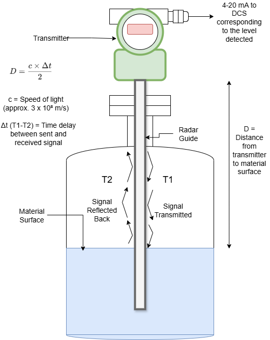
A simplified block diagram illustrating the principles of Non-Contacting and Guided Wave Radar.
Advantages of Radar Level Measurement
Unaffected by Process Conditions: Radar measurement is largely unaffected by changes in process fluid density, temperature, pressure, and vapor space conditions.
High Accuracy and Reliability: Radar provides highly accurate and repeatable level measurements.
No Moving Parts: With no moving components, maintenance requirements are significantly lower compared to displacers.
Non-Contact (for non-contacting radar): As there is no contact with the process fluid, it is ideal for corrosive, sticky, or abrasive materials.
Handles Foam and Turbulence (especially GWR): Guided Wave Radar is particularly adept at providing reliable measurements in challenging conditions like foam, vapor, and turbulence.
Disadvantages of Radar Level Measurement
Higher Initial Cost: The initial purchase price of a radar transmitter is typically higher than that of a DP transmitter.
Dielectric Constant Limitations: The reflectivity of the microwave pulse depends on the dielectric constant of the material. Very low dielectric constant materials can be challenging to measure.
Installation Considerations: Proper installation is crucial to avoid false echoes from internal tank obstructions.
Ideal Applications for Radar Level Measurement
A wide variety of liquid and solid level measurement applications.
Challenging process conditions with changing density, temperature, or pressure.
Applications with corrosive, viscous, or abrasive fluids.
Inventory tanks requiring high accuracy.
Applications with foam, vapor, or turbulence.
Head-to-Head Comparison: Displacer vs. DP vs. Radar
Making the Right Choice: A Decision Framework
Choosing the optimal level measurement technology requires a careful evaluation of your specific application. Here are some key questions to guide your decision:
What is the material being measured?
Clean Liquid, Constant Density: Displacer or DP could be suitable.
Corrosive, Sticky, or Abrasive: Non-contacting Radar is a strong contender.
Solids or Powders: Radar is often the best choice.
Interface between two liquids: Displacer is a traditional choice, but GWR can also be very effective.
What are the process conditions?
Varying Temperature, Pressure, or Density: Radar is the most reliable option.
Foam, Vapor, or Turbulence: Guided Wave Radar excels in these conditions.
High Temperature and Pressure: All three technologies can be engineered for these conditions, but the implementation for DP and Displacer can be more complex.
What are your accuracy and maintenance requirements?
High Accuracy Needed: Radar is generally the most accurate.
Low Maintenance is a Priority: Radar’s lack of moving parts makes it a clear winner.
What is your budget?
Lowest Initial Cost: DP is typically the most budget-friendly option upfront. However, consider the total cost of ownership, including installation and maintenance.
The Future is Smart and Wireless
The evolution of level measurement technology doesn’t stop here. The integration of WirelessHART and other wireless protocols is making installation easier and more cost-effective. Furthermore, advanced diagnostics and the integration with Industrial Internet of Things (IIoT) platforms are providing deeper insights into process performance and predictive maintenance needs.
Conclusion: The Right Tool for the Job
There is no single “best” level measurement technology. The optimal choice is always the one that best fits the specific requirements of the application.
Displacer technology, while older, still holds its own in specific niches like clean liquid interface measurement.
DP remains a cost-effective workhorse for simpler applications with stable process conditions.
Radar, with its high accuracy, reliability, and immunity to changing process conditions, has become the go-to technology for a vast and growing range of applications, especially the more challenging ones.
By carefully considering the factors outlined in this guide, you can confidently select the level measurement technology that will provide safe, reliable, and efficient operation for years to come.