DP Level Transmitter Range Selection (mmWC) — Worked Examples
This page shows practical DP level range calculations for: Open Tank, Closed Tank (Dry Leg), Closed Tank (Wet Leg), Closed Tank with Elevation (Wet Leg), and Closed Tank with Suppression — with full breakdown and sample numbers.
Global Assumptions & Conversions
- Gravity: g = 9.81 m/s²
- Key formula: ΔP = ρ × g × h
- Water column conversion: 1 mmWC = 9.81 Pa
- Convert Pa to mmWC: mmWC = ΔP(Pa) / 9.81
Sample data used in worked examples:
Level range (H) = 0 to 3.0 m
Process liquid density (ρp) = 1000 kg/m³ (water)
Wet leg density (ρwl) = 1000 kg/m³ (water)
General DP Relationship (All Cases)
A DP transmitter measures:
ΔP = P(HP) − P(LP)
P = ρ × g × h
mmWC = Pa / 9.81
Where HP is the bottom connection pressure, LP is the top connection pressure reference (atmosphere / vapor space / wet leg).
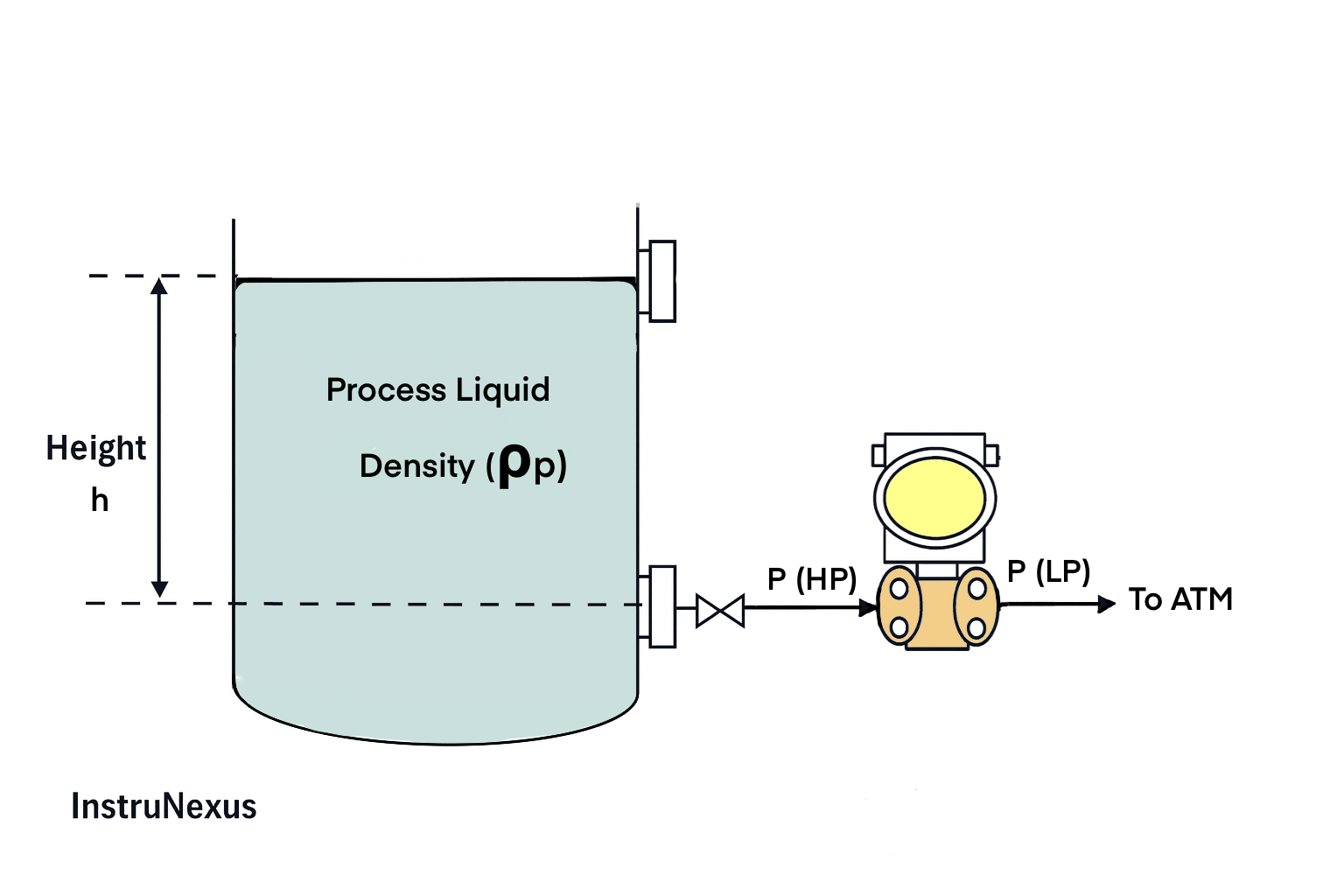
1) Open Tank (LP Vented to Atmosphere)
Concept
LP side is vented to atmosphere, so P(LP) = 0 (gauge reference). DP is only due to liquid head at the bottom tap.
Formulas
P(HP) = ρp × g × h
P(LP) = 0
ΔP = P(HP) − P(LP) = ρp × g × h
LRV = ΔP at h = 0%
URV = ΔP at h = 100%
Sample Calculation (0 to 3.0 m water)
Given: ρp = 1000 kg/m³, g = 9.81 m/s², level h = 0 to 3.0 m

At 0% (h = 0 m):
ΔP = 1000 × 9.81 × 0 = 0 Pa
LRV = 0 / 9.81 = 0 mmWC

At 100% (h = 3.0 m):
ΔP = 1000 × 9.81 × 3.0 = 29430 Pa
URV = 29430 / 9.81 = 3000 mmWC

Range: 0 to 3000 mmWC
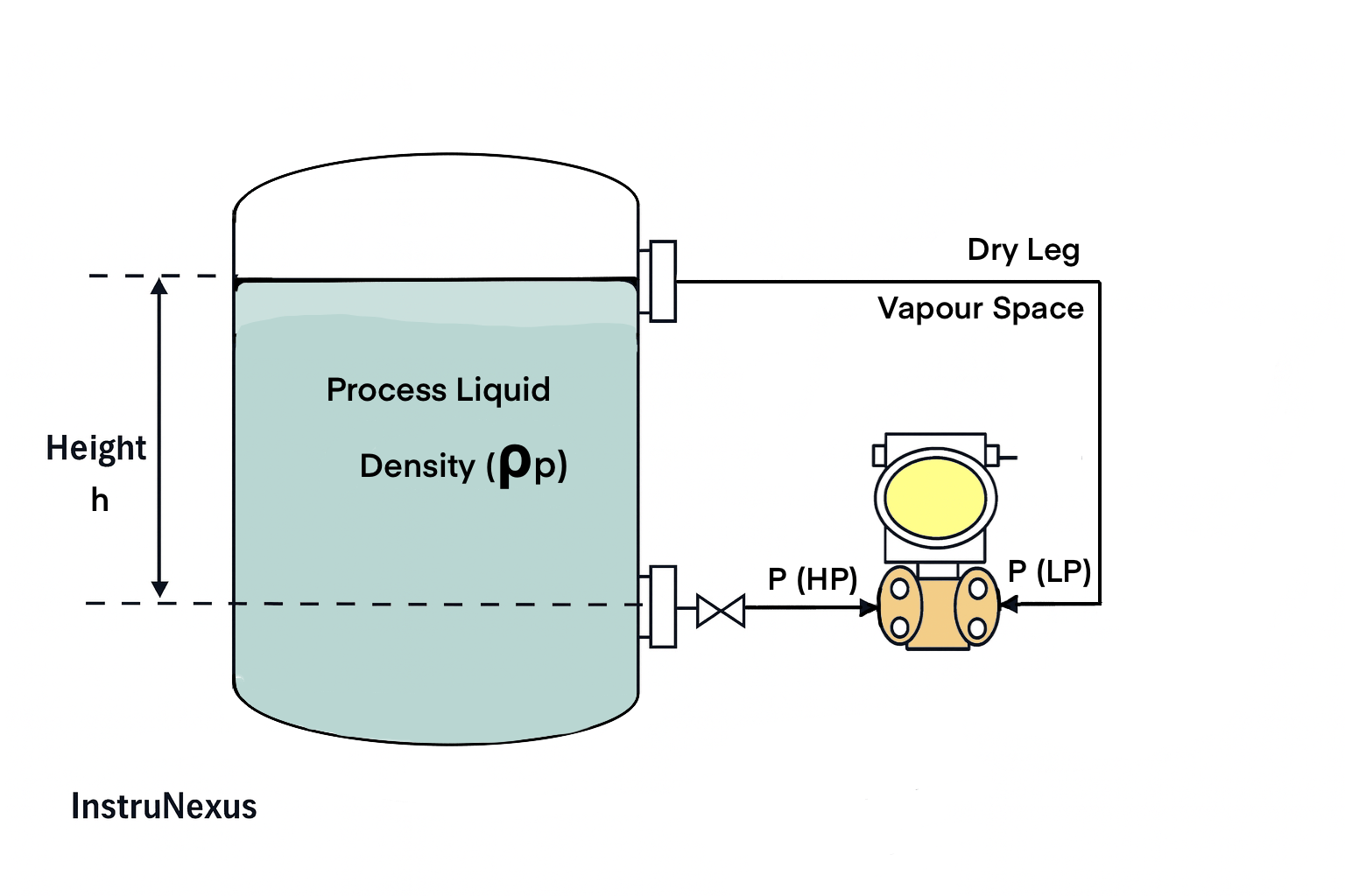
2) Closed Tank (Dry Leg on LP)
Concept
LP is connected to the vapor space at the top of the tank with a dry impulse line. Gas density is negligible, so the LP head is typically neglected for range selection (P(LP) ≈ 0 gauge).
Formulas
P(HP) = ρp × g × h
P(LP) ≈ 0   (gas head neglected)
ΔP = ρp × g × h
LRV = ΔP at h = 0%
URV = ΔP at h = 100%
Sample Calculation (0 to 3.0 m water)
Given: ρp = 1000 kg/m³, g = 9.81 m/s², level h = 0 to 3.0 m

At 0% (h = 0 m):
ΔP = 1000 × 9.81 × 0 = 0 Pa
LRV = 0 / 9.81 = 0 mmWC

At 100% (h = 3.0 m):
ΔP = 1000 × 9.81 × 3.0 = 29430 Pa
URV = 29430 / 9.81 = 3000 mmWC

Range: 0 to 3000 mmWC
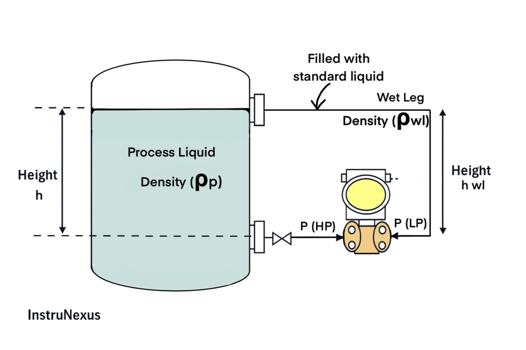
3) Closed Tank (Wet Leg on LP) — General Case
Concept
In a wet leg, the LP impulse line is intentionally kept filled with liquid (often condensate). This creates a constant LP pressure head that must be subtracted from the HP pressure.
Formulas
P(HP) = ρp  × g × h
P(LP) = ρwl × g × hwl   (constant wet leg head)

ΔP = P(HP) − P(LP)
ΔP = (ρp × g × h) − (ρwl × g × hwl)

LRV = (ρp × g × h at 0%)   − (ρwl × g × hwl)
URV = (ρp × g × h at 100%) − (ρwl × g × hwl)
Note: Wet leg calculations often produce a negative LRV (called elevated zero), because LP constant head can be larger than HP at low levels.

4) Closed Tank with Elevation (Wet Leg on LP) — Worked Example
Given (Example)
- Process level range, h = 0 to 3.0 m
- Process density, ρp = 1000 kg/m³
- Wet leg density, ρwl = 1000 kg/m³
- Wet leg height on LP side, hwl = 3.0 m
- g = 9.81 m/s²
Formulas
P(LP) = ρwl × g × hwl    (constant)
P(HP) = ρp  × g × h
ΔP = P(HP) − P(LP)
mmWC = Pa / 9.81
Step-by-step Sample Calculation
Step 1: LP constant pressure (wet leg)
P(LP) = 1000 × 9.81 × 3.0 = 29430 Pa
P(LP) in mmWC = 29430 / 9.81 = 3000 mmWC (constant)

Step 2: LRV at 0% (h = 0 m)
P(HP) = 1000 × 9.81 × 0 = 0 Pa
ΔP = P(HP) − P(LP) = 0 − 29430 = −29430 Pa
LRV = −29430 / 9.81 = −3000 mmWC

Step 3: URV at 100% (h = 3.0 m)
P(HP) = 1000 × 9.81 × 3.0 = 29430 Pa
ΔP = 29430 − 29430 = 0 Pa
URV = 0 / 9.81 = 0 mmWC

Range (Elevation / elevated zero): −3000 to 0 mmWC
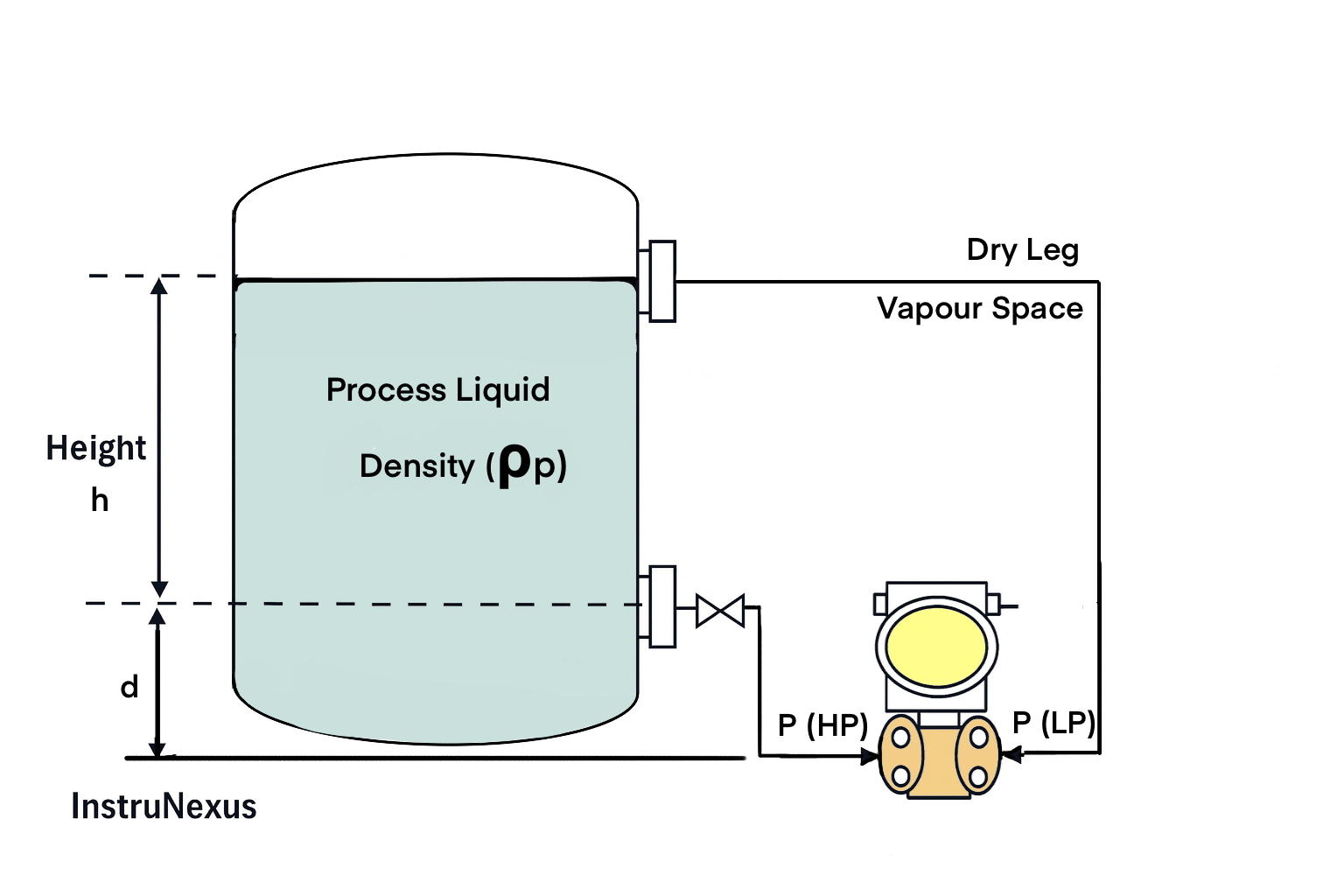
5) Closed Tank with Suppression (Transmitter Below Bottom Tap)
Concept
Suppression happens when the HP side sees a constant additional head (for example, transmitter mounted below the bottom nozzle). This shifts the LRV to a positive value (called suppressed zero).
Given (Example)
- Process level range, h = 0 to 3.0 m
- Transmitter is mounted d = 0.8 m below the bottom tap (HP leg always full of liquid)
- ρp = 1000 kg/m³, g = 9.81 m/s²
- LP is dry leg: P(LP) ≈ 0
Formulas
Total HP head height = d + h

P(HP) = ρp × g × (d + h)
P(LP) ≈ 0
ΔP = P(HP) − P(LP) = ρp × g × (d + h)

LRV = ΔP at h = 0%
URV = ΔP at h = 100%
mmWC = Pa / 9.81
Step-by-step Sample Calculation
Given: ρp = 1000 kg/m³, g = 9.81 m/s², d = 0.8 m, level h = 0 to 3.0 m

At 0% (h = 0 m):
ΔP = 1000 × 9.81 × (0.8 + 0) = 7848 Pa
LRV = 7848 / 9.81 = 800 mmWC

At 100% (h = 3.0 m):
ΔP = 1000 × 9.81 × (0.8 + 3.0) = 37278 Pa
URV = 37278 / 9.81 = 3800 mmWC

Range (Suppression / suppressed zero): +800 to +3800 mmWC