An in-depth exploration of the critical machinery that powers the global energy supply, this article delves into the essential process equipment used in oil and gas facilities. From the initial separation of well fluids to the final refining of commercial products, each piece of equipment plays a vital role in ensuring safe, efficient, and profitable operations. This guide will walk you through the function, significance, and operational principles of this machinery, complete with diagrams to illustrate their place in the process flow.
An Introduction to Oil and Gas Process Equipment
The journey of oil and gas from deep within the earth to its final form as fuel, plastics, or other valuable commodities is a complex and highly engineered process. This transformation happens within sprawling industrial facilities, both onshore and offshore, that are packed with a vast array of specialized equipment. This machinery is designed to operate under extreme pressures and temperatures, handling materials that can be corrosive, flammable, and hazardous.
Understanding this equipment is not just for chemical or petroleum engineers; it’s for anyone interested in the energy sector. The reliability and efficiency of these assets directly impact global energy prices, environmental safety, and the economic viability of entire projects. This article will serve as a comprehensive guide, breaking down the most critical types of process equipment, what they do, and why they are so important. We will explore the core machinery that underpins the upstream (exploration and production), midstream (transportation and storage), and downstream (refining and processing) sectors of the industry.
Separation Equipment: The First Crucial Step
The very first stage in processing crude oil and natural gas is to separate the raw stream into its primary components: oil, gas, and water. This is the fundamental role of separation equipment. The fluid mixture emerging from a wellhead is a high-pressure, turbulent blend of hydrocarbon liquids, hydrocarbon gas, water, and often solids like sand or silt. Separators are designed to untangle this complex mixture, providing distinct streams that can be further processed.
The primary principle behind separation is gravity. Just as oil and vinegar separate in a salad dressing, the denser liquids (water and oil) will settle at the bottom while the lighter gas rises to the top. The design of a separator vessel is optimized to allow enough residence time for this natural separation to occur.
Key Types of Separators:
Two-Phase Separators: These are the simplest type, designed to separate a gas from a liquid. They are commonly used in applications where the liquid is primarily oil or primarily water, but not a significant mixture of both.
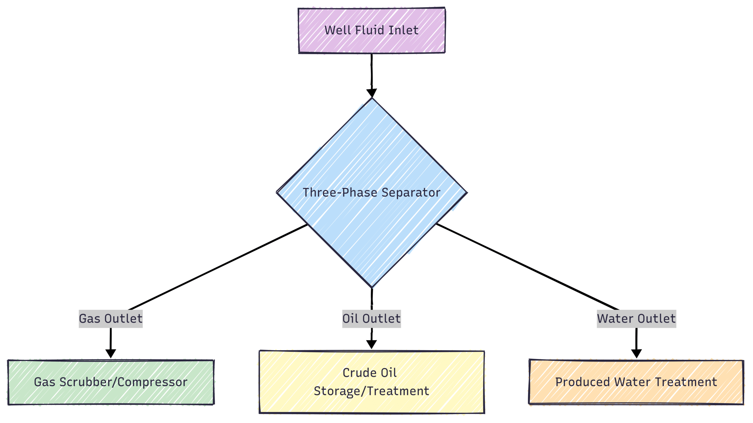
Three-Phase Separators: This is the most common type in oil production facilities. These vessels are designed to separate the well stream into three distinct phases: oil, gas, and free water. They feature internal components like weirs and baffles to carefully control the fluid levels and ensure a clean separation.
Scrubbers and Knockout Drums: These are specialized types of separators designed to handle fluid streams with a very high gas-to-liquid ratio. Their primary goal is to “scrub” or “knock out” small amounts of entrained liquid from a gas stream to protect downstream equipment like compressors.
A typical three-phase separation process can be visualized as follows:
Maintenance and Operational Considerations: Proper functioning of separators is critical. Issues like foaming, paraffin wax buildup, and corrosion can severely impact efficiency. Regular internal inspections, monitoring of fluid levels and pressures, and chemical injection programs are essential to keep these vital assets operating as designed.
Heat Transfer Equipment: Managing Thermal Energy
Controlling temperature is fundamental to almost every process in an oil and gas facility. Whether it’s heating crude oil to reduce its viscosity for easier pumping, cooling gas to condense valuable liquids, or reboiling liquids in a distillation column, heat transfer equipment is ubiquitous. The goal is always to move thermal energy from a hotter fluid to a colder one in a controlled and efficient manner.
The most common type of heat transfer equipment is the heat exchanger. These devices are designed to maximize the surface area between two fluids while keeping them from mixing, allowing heat to conduct and convect from one to the other.
Common Types of Heat Exchangers:
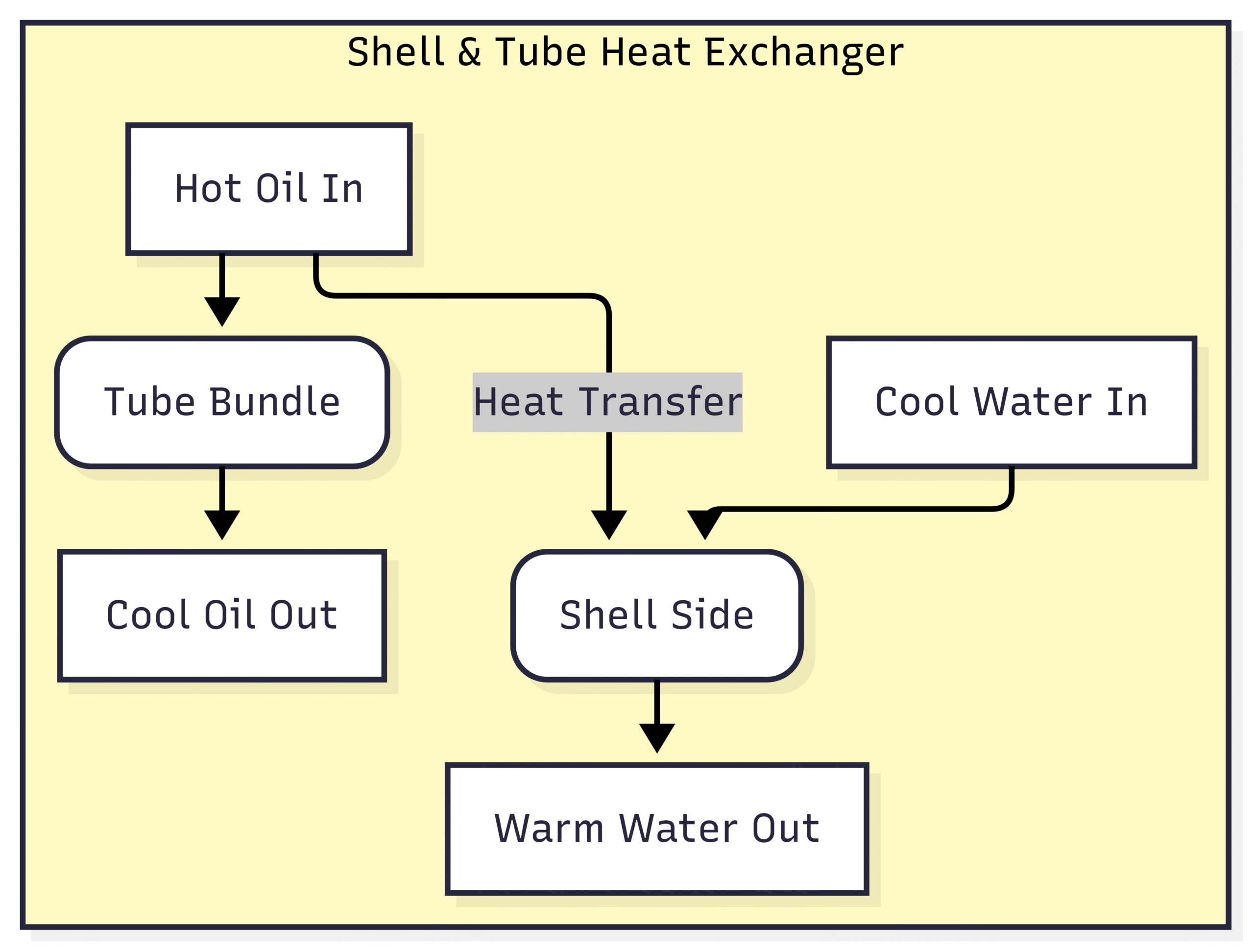
Shell and Tube Heat Exchangers: This is the workhorse of the process industry. It consists of a large cylindrical shell that encloses a bundle of tubes. One fluid flows through the tubes, while the other flows over the tubes within the shell. Their robust design makes them suitable for high-pressure and high-temperature applications.
Plate and Frame Heat Exchangers: These consist of a series of thin, corrugated metal plates bolted together. The fluids flow in the narrow channels between the plates. They are highly efficient and compact but are generally used for lower pressure and temperature services compared to shell and tube exchangers.
Air-Cooled Heat Exchangers (Fin-Fan Coolers): In locations where cooling water is scarce, such as arid regions or offshore platforms, air-cooled exchangers are used. These devices use fans to force ambient air over a series of finned tubes containing the hot process fluid, similar to a car radiator.
Here is a simplified diagram showing how a heat exchanger might be used to cool a hot oil stream using cooler water:
Significance in Processing: Effective heat management is crucial for energy efficiency and process optimization. Re-using waste heat from one process to heat another stream (a practice known as heat integration or pinch analysis) can dramatically reduce a facility’s fuel consumption and operating costs. For example, the hot products leaving a distillation column are often used to preheat the feed entering the column, saving enormous amounts of energy.
Fluid Handling Equipment: The Heartbeat of the Facility
If separators are the lungs of a facility, then pumps and compressors are its heart, tirelessly working to move fluids from one process unit to another. Without this essential fluid handling equipment, everything would grind to a halt. While both move fluids, they are distinguished by the state of the fluid they handle:
Pumps are designed to move liquids.
Compressors are designed to move gases.
Pumps
Pumps are used for everything from transporting crude oil over hundreds of miles in pipelines to injecting small amounts of chemicals into a process stream. They work by adding energy to the liquid to increase its pressure, allowing it to overcome friction and elevation changes.
Major Pump Categories:
Centrifugal Pumps: These are the most common type of pump in the oil and gas industry. They use a rapidly rotating impeller to accelerate the liquid, converting velocity into pressure. They are reliable and can handle a wide range of flow rates and pressures.
Positive Displacement (PD) Pumps: Unlike centrifugal pumps, PD pumps trap a fixed volume of liquid and then force it into the discharge pipe. They are used for applications requiring very high pressures or precise flow rates (e.g., chemical injection). Common types include reciprocating pumps and rotary pumps (like gear or screw pumps).
Compressors
Compressors perform the same function as pumps but for gases. By reducing the volume of a gas, they increase its pressure. This is a critical operation for transporting natural gas through pipelines, re-injecting gas into a reservoir to enhance oil recovery, or feeding gas to a processing unit like a cryogenic plant.
Major Compressor Categories:
Centrifugal Compressors: Similar in principle to centrifugal pumps, these use a rotating impeller to impart velocity to the gas, which is then converted to pressure. They are used for high-volume, continuous-flow applications.
Reciprocating Compressors: These are positive displacement machines that use a piston moving back and forth in a cylinder to compress the gas. They are typically used for lower flow rates but can achieve very high discharge pressures.
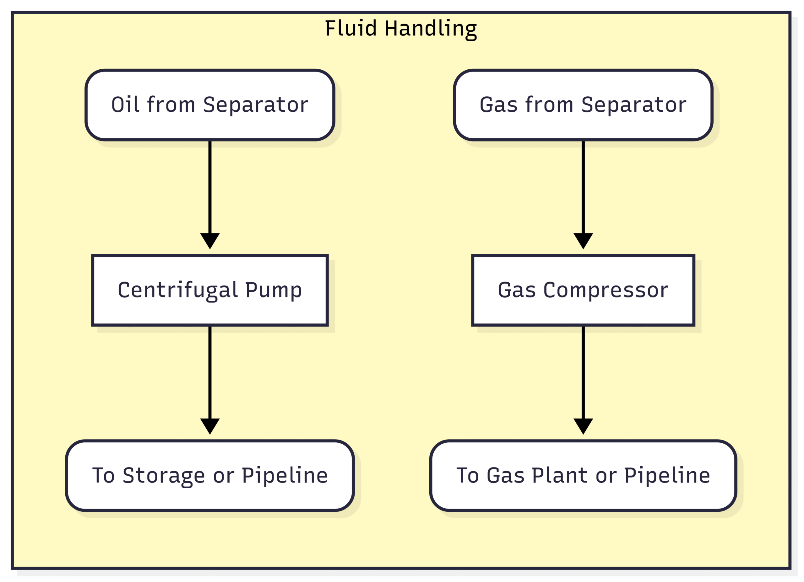
The following diagram illustrates the role of a pump and compressor after the initial separation stage:
Operational Challenges: Both pumps and compressors are complex rotating equipment that require diligent monitoring and maintenance. Common issues include seal leaks, bearing failures, and vibration problems. For compressors, ensuring the incoming gas is free of liquids is paramount, as ingesting liquids (a condition known as “slugging”) can cause catastrophic mechanical failure.
Reaction and Conversion Equipment: The Chemistry of Refining
While the equipment discussed so far is primarily focused on physical separation and transportation, the downstream sector of the oil and gas industry is defined by chemical transformation. This is where reaction and conversion equipment, primarily reactors, comes into play. These are the vessels where crude oil fractions are chemically altered to create more valuable products.
Reactors are designed to provide a controlled environment—specific temperatures, pressures, and residence times—for chemical reactions to occur, often in the presence of a catalyst. A catalyst is a substance that speeds up a chemical reaction without being consumed by it.
Key Downstream Reactor Types:
Fluid Catalytic Cracker (FCC): The FCC unit is one of the most important conversion units in a modern refinery. It “cracks” large, heavy hydrocarbon molecules from crude oil into smaller, more valuable molecules like gasoline and diesel fuel. It uses a fine powder catalyst that is fluidized (behaving like a liquid) and circulated between the reactor and a regenerator.
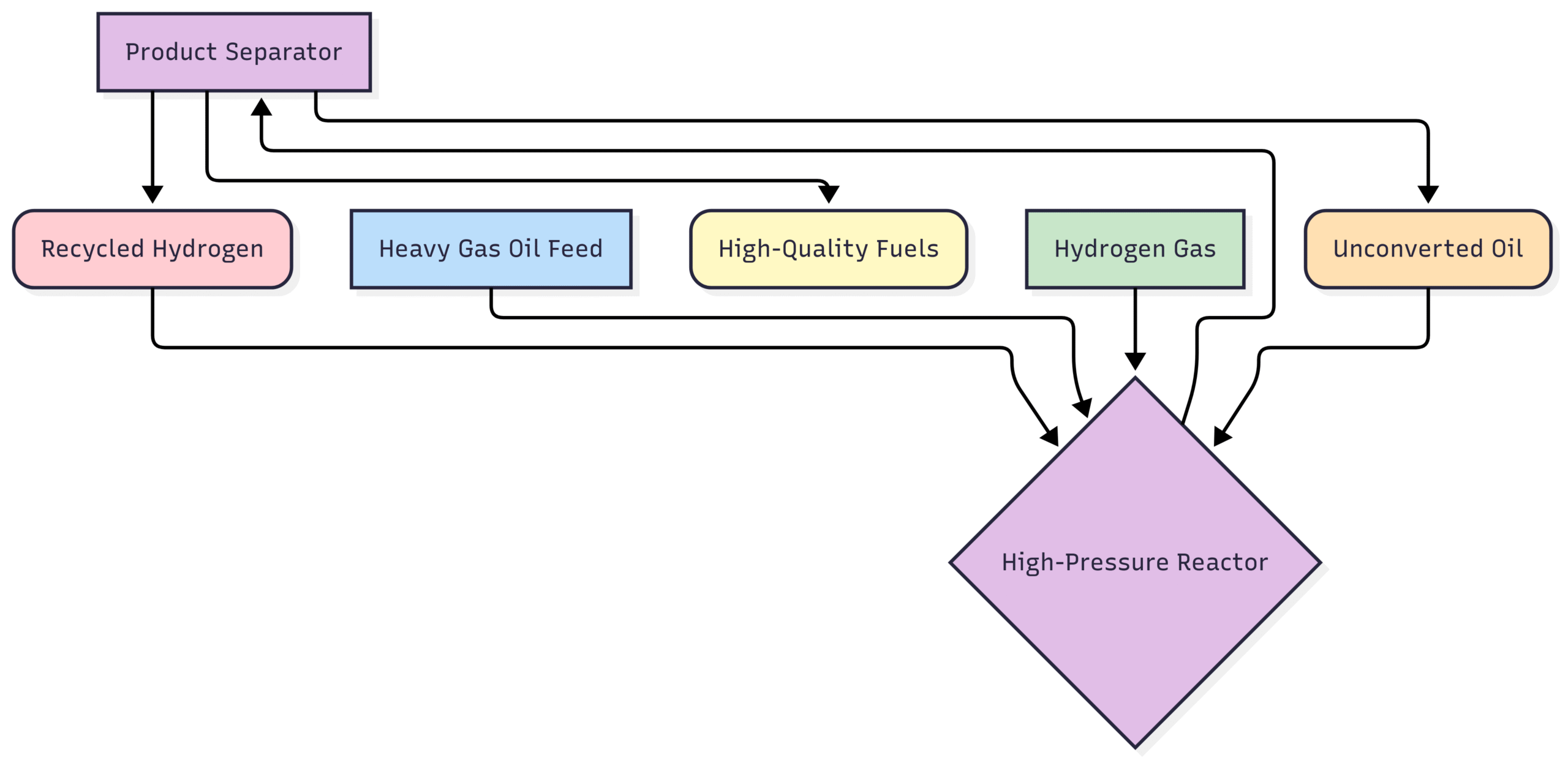
Hydrocrackers: These reactors also break down heavy oils but do so in a high-pressure, hydrogen-rich environment. Hydrocracking is more versatile than FCC and can produce high-quality jet fuel and diesel.
Reforming Reactors: These units are used to upgrade low-octane naphtha into high-octane gasoline blending components through a series of catalytic reactions that rearrange the hydrocarbon molecules.
A simplified flow for a hydrocracking unit could be:
The design and operation of these reactors are incredibly complex, involving a deep understanding of chemical kinetics, thermodynamics, and material science. The choice of catalyst is critical to the yield and quality of the products.
Treatment and Purification Units: Polishing the Product
Before oil and gas products can be sold, they must meet strict quality and environmental specifications. This often requires removing impurities, a process carried out in treatment and purification units. These units target specific contaminants that can be corrosive, hazardous, or would inhibit further processing.
Essential Treatment Processes:
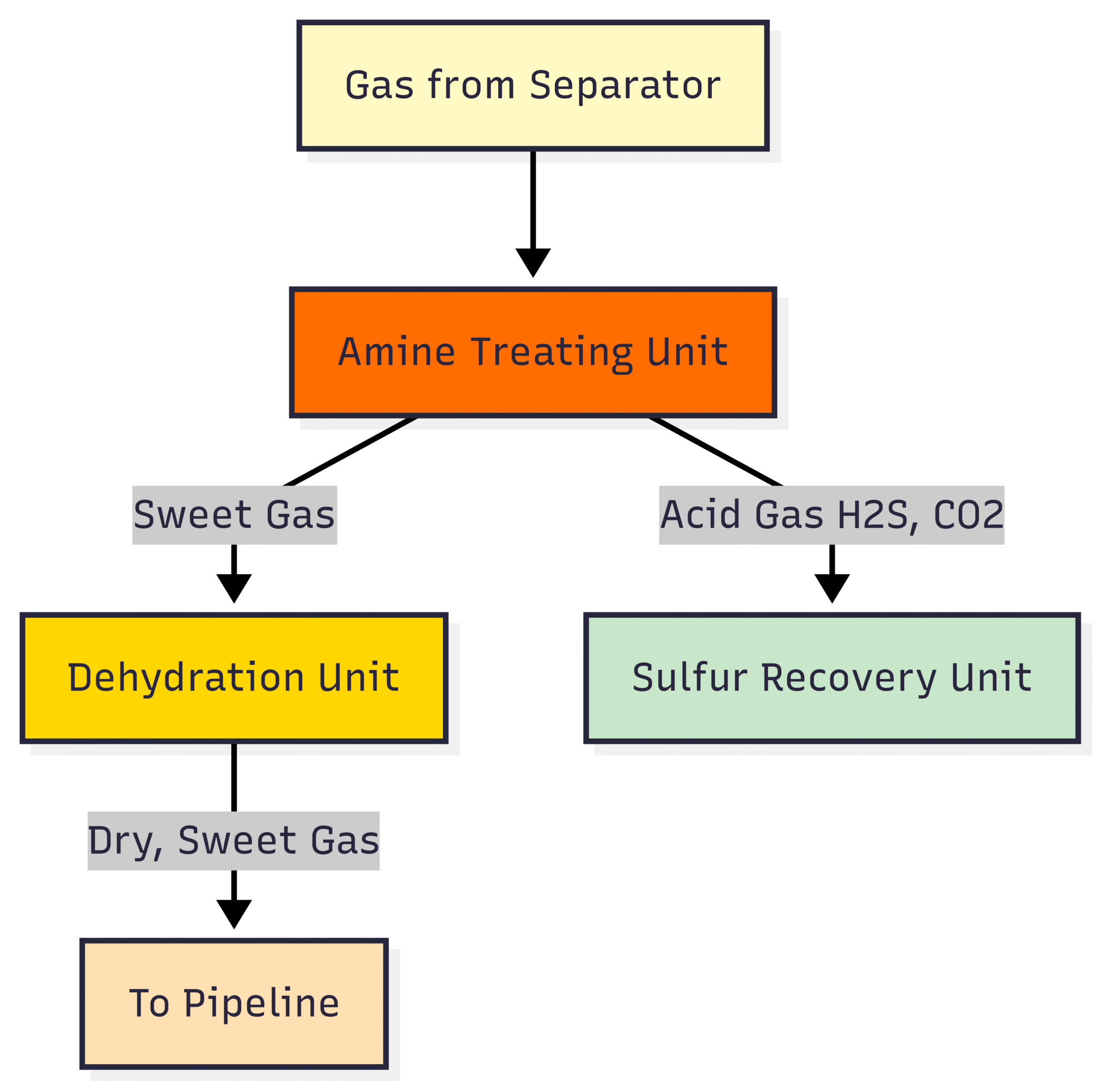
Gas Dehydration: Natural gas from a reservoir is saturated with water vapor. If not removed, this water can form solid hydrates (ice-like structures) that can plug pipelines and equipment, especially in cold climates. Dehydration is typically achieved using triethylene glycol (TEG) contactors, which absorb the water from the gas.
Gas Sweetening (Amine Treating): Natural gas and crude oil often contain sulfur compounds, primarily hydrogen sulfide (H₂S), and carbon dioxide (CO₂). These are called “acid gases” and make the gas “sour.” Sour gas is highly corrosive and toxic. Amine treating units use a solvent (an amine solution) to absorb the H₂S and CO₂ from the sour gas stream, “sweetening” it.
Desalters: Crude oil coming from a separator often contains salt water emulsified within it. This salt (primarily sodium chloride) can cause severe corrosion and foul heat exchangers and reactor catalysts in the refinery. An electrostatic desalter is a vessel that applies a high-voltage electric field to the oil, causing the water droplets to coalesce and settle out for removal.
This diagram shows where treatment units fit into the overall gas processing flow:
Environmental and Safety Importance: Treatment units are not just about meeting product specifications; they are also critical for environmental compliance and safety. The removal of sulfur compounds, for example, prevents the release of sulfur dioxide (a major contributor to acid rain) when the fuels are combusted.
Storage and Transportation: The Final Leg of the Journey
Once the oil and gas have been processed and treated, they must be stored and transported to markets, which can be thousands of miles away.
Storage Tanks: The most visible pieces of equipment at many facilities are the large atmospheric storage tanks. These cylindrical tanks with either fixed or floating roofs store crude oil and refined liquid products at atmospheric pressure. Floating roofs are often used for volatile products like gasoline to minimize vapor emissions.
Pipelines: For overland transportation, pipelines are the most efficient and safest method for moving large quantities of oil, gas, and refined products. The entire pipeline system relies on the pumps and compressors discussed earlier to keep the fluids moving.
Conclusion: An Integrated System of Critical Assets
The equipment used in oil and gas facilities represents a triumph of modern engineering, designed for safety, efficiency, and longevity in some of the most challenging operating conditions imaginable. From the initial separation of wellhead fluids to the final treatment and storage of commercial-grade products, each piece of machinery—separators, heat exchangers, pumps, compressors, reactors, and treaters—is an indispensable link in a long and complex chain.
Understanding these essential titans of the industry provides a deeper appreciation for the intricate process of converting a raw natural resource into the energy and products that fuel our world. Their continued reliable operation, driven by diligent maintenance and technological innovation, will remain the bedrock of the global energy landscape for the foreseeable future.
Excellent, thanks