Feedforward Control: Anticipating Your Way to Precision
In the intricate world of industrial automation and control systems, achieving and maintaining precise control over processes is paramount. While the ubiquitous feedback control loop – think of your home thermostat – is often the first concept that comes to mind, there’s another powerful strategy that often works in conjunction or even independently to achieve superior performance: feedforward control.
Imagine trying to drive a car while only looking in the rearview mirror. You’d constantly be reacting to where you’ve been, making corrections after the fact. Feedback control, in many ways, is like this. It observes the output, compares it to the desired setpoint, and then adjusts the input to correct any errors. While incredibly effective for many applications, it inherently involves a delay as it waits for an error to manifest.
Now, imagine if you had a crystal ball that could predict upcoming turns, changes in road conditions, or even the actions of other drivers. You could then proactively adjust your steering, acceleration, or braking before the need for a correction even arises. This, in essence, is the magic of feedforward control: anticipating disturbances and making pre-emptive adjustments to minimize their impact.
In this comprehensive guide, we’ll delve deep into the principles of feedforward control, exploring its mechanisms, advantages, disadvantages, practical applications, and how it often harmonizes with feedback control to create robust and highly responsive control systems. We’ll aim for a detailed exploration, going beyond the basics to provide you with a solid understanding, supported by practical examples and visual aids.
The Fundamental Flaw of Feedback
Before we fully embrace feedforward, let’s briefly revisit the inherent limitation of purely feedback-based systems. Consider a simple heating process where you want to maintain a constant temperature in a chemical reactor.
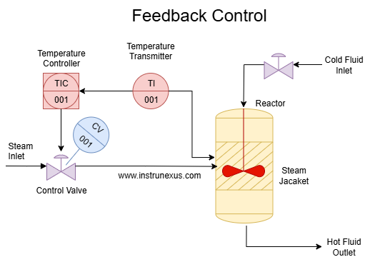
In a pure feedback control loop, a sensor measures the current temperature (e.g., 75.0 °C). This measured value is compared to the desired setpoint (e.g., 80 °C) by a comparator. The difference, or error signal, is then fed to a PID controller. The PID controller processes this error and sends a control signal to a heater control valve, which adjusts the heater to reduce the error.
Let’s say the setpoint is 80°C. If a sudden influx of cold reactants enters the reactor, the temperature will drop. The feedback control system, with its temperature sensor, will detect this drop after it has occurred. It will then generate an error signal, and the controller will react by increasing the heat input to bring the temperature back up to the setpoint.
The problem? During the time it takes for the temperature to drop, be detected, and for the heater to compensate, the process variable (temperature) has deviated from the setpoint. This transient deviation can be undesirable, leading to off-spec product, process inefficiencies, or even safety concerns in sensitive applications. This “lag” or “overshoot/undershoot” is an inherent characteristic of feedback control when faced with significant or rapid disturbances.
Enter Feedforward Control:
Feedforward control aims to address this very limitation. Instead of waiting for a disturbance to affect the process variable and then reacting, a feedforward controller attempts to measure the disturbance before it impacts the process and then takes corrective action. It’s about being proactive rather than reactive.
Now, let’s incorporate feedforward control into our chemical reactor example.
The Key Idea: Identify the disturbance and measure it.
In our heating process, the primary disturbance is the temperature of the incoming reactants. If we can measure this incoming temperature before it enters the reactor, we can anticipate its effect.
How it Works (Conceptually):
Measure the Disturbance: A sensor is placed to measure the temperature of the incoming cold flow.
Calculate the Required Compensation: Based on a known model of the process, the feedforward controller calculates how much the heater input needs to change to counteract the effect of the incoming cold flow and maintain the desired reactor temperature.
Apply the Compensation: This calculated adjustment is then sent directly to the heater control valve, before the cold flow significantly impacts the reactor temperature.
This means that by the time the cold flow actually mixes in the reactor, the heater has already been adjusted to compensate, ideally preventing any significant drop in the reactor’s main temperature.
The Anatomy of a Feedforward Control System
A typical feedforward control system involves several key components:
Disturbance Sensor: This measures the primary disturbance variable. The accuracy and speed of this sensor are crucial for effective feedforward control.
Feedforward Controller: This is the “brain” of the feedforward system. It contains a mathematical model of the process that describes how the disturbance affects the controlled variable. Based on the disturbance measurement and this model, it calculates the necessary control action.
Control Actuator: This receives the command from the feedforward controller and directly manipulates the process to counteract the disturbance.

It’s important to note that feedforward control rarely works in isolation. It’s almost always combined with a feedback controller. Why? Because the feedforward model is never perfect. There will always be unmeasured disturbances, inaccuracies in the model, or changes in process parameters that the feedforward controller cannot account for. The feedback loop then acts as a “trim” or “fine-tuning” mechanism, correcting any residual errors that the feedforward controller misses.
In a combined feedforward-feedback system, the feedforward controller provides the bulk of the control action to quickly mitigate known disturbances, while the feedback controller provides the precision and robustness to handle unmeasured disturbances and model inaccuracies.
Advantages of Feedforward Control
The benefits of implementing feedforward control can be significant:
Faster Disturbance Rejection: This is the most prominent advantage. By acting preemptively, feedforward control can significantly reduce or even eliminate deviations in the controlled variable caused by measurable disturbances. This leads to much quicker recovery times compared to purely feedback systems.
Reduced Settling Time: Processes reach and maintain their setpoint faster, leading to increased efficiency and throughput.
Improved Product Quality: By maintaining process variables closer to their setpoints, feedforward control can lead to more consistent and higher-quality products. In many industries (e.g., chemical, pharmaceutical), even small deviations can impact product specifications.
Reduced Actuator Wear: Because control actions are more precise and less erratic, actuators (like valves or heaters) experience less unnecessary movement and wear, potentially extending their lifespan.
Handles Non-Minimum Phase Systems Better: Some processes exhibit “inverse response” or “non-minimum phase” behavior, where an initial control action causes the process variable to move in the opposite direction before eventually settling. Feedback controllers struggle with these, often leading to oscillations. Feedforward can be designed to compensate for these tricky dynamics.
Effective for Long Dead-Time Processes: In processes with significant dead time (time delay between input change and output response), feedback control is notoriously difficult to tune and can become unstable. Feedforward, by acting preemptively, can effectively compensate for dead time by making adjustments in advance.
Disadvantages and Limitations of Feedforward Control
While powerful, feedforward control is not a silver bullet and comes with its own set of challenges:
Requires Knowledge of Disturbances: You must be able to identify and accurately measure the significant disturbances affecting your process. If a disturbance cannot be measured, feedforward cannot compensate for it.
Requires a Process Model: A reasonably accurate mathematical model of how the disturbance affects the controlled variable is essential. Developing this model can be complex and time-consuming, often requiring process identification techniques, first-principles modeling, or extensive experimentation.
Model Accuracy is Crucial: The effectiveness of feedforward control is directly proportional to the accuracy of its process model. If the model is inaccurate, the feedforward action will be incorrect, potentially making the situation worse.
Sensitivity to Model Changes: Process parameters can change over time due to aging equipment, catalyst deactivation, fouling, or changes in operating conditions. If the feedforward model is not updated to reflect these changes, its performance will degrade. This often necessitates adaptive feedforward strategies.
Not Robust to Unmeasured Disturbances: Feedforward control can only compensate for the disturbances it measures. Any unmeasured disturbance will pass through the system unaddressed, necessitating the presence of a feedback loop.
Increased Instrumentation Costs: Implementing feedforward control often requires additional sensors to measure disturbances, increasing the initial cost of the control system.
Tuning Complexity: While the concept is straightforward, tuning a feedforward controller, especially in combination with feedback, can be more complex than tuning a standalone feedback controller.
Where to Apply Feedforward Control: Practical Examples
Feedforward control shines in applications where:
There are known, measurable disturbances.
The process dynamics are reasonably well understood.
Tight control and rapid disturbance rejection are critical.
Processes have significant dead time.
Let’s explore some practical examples across various industries:
1. Heat Exchangers: Temperature Control
Scenario: Maintaining a constant outlet temperature of a fluid from a heat exchanger, despite variations in the inlet temperature of the heating medium or the process fluid.
Disturbance: Inlet temperature of the process fluid (e.g., cold feed stream).
Feedforward Action: A sensor measures the inlet temperature of the process fluid. If the inlet temperature drops, the feedforward controller immediately increases the flow rate of the heating medium (e.g., steam) to compensate before the outlet temperature starts to fall.
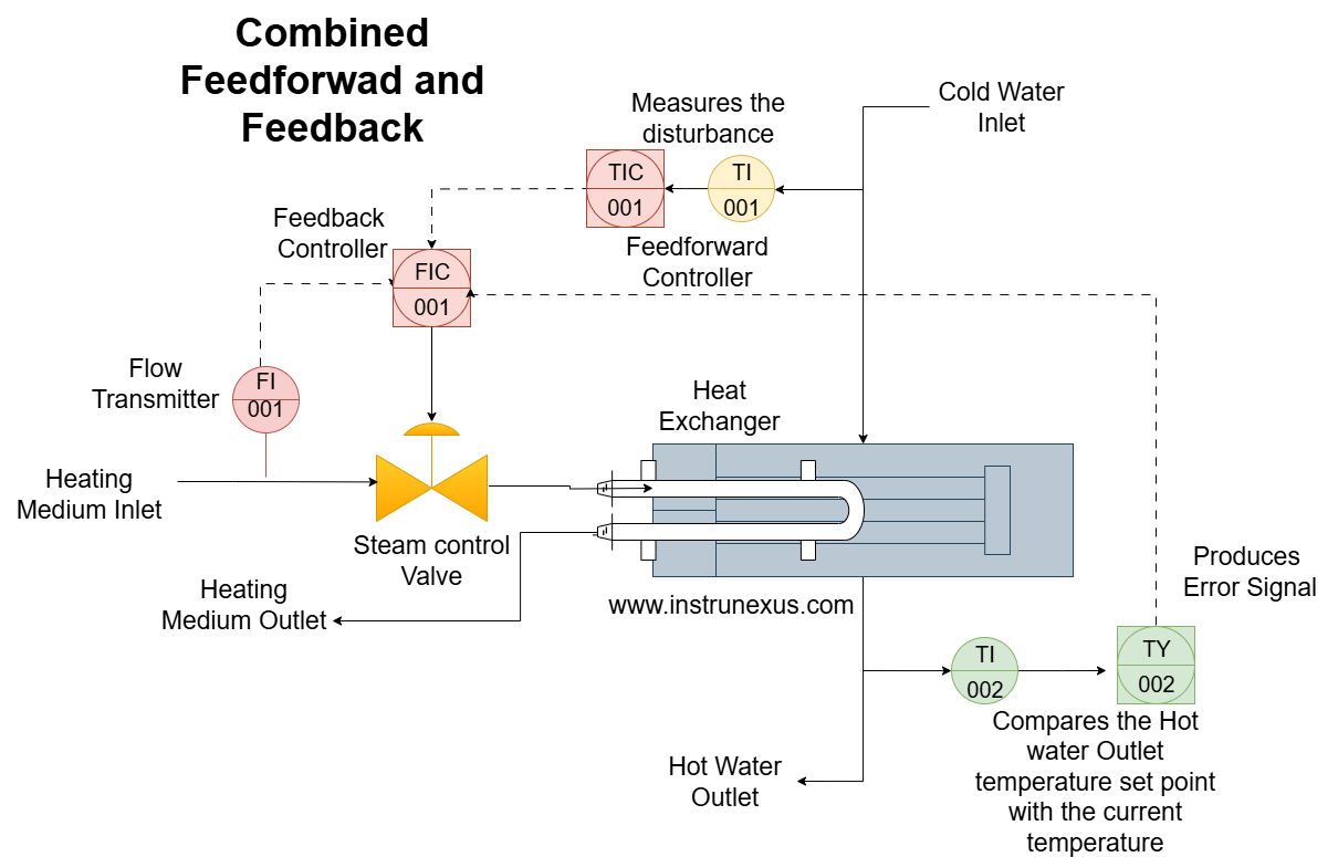
This diagram illustrates a combined feedforward-feedback control scheme for a heat exchanger. The primary goal is to maintain a constant outlet temperature of the process fluid.
Components:
Heat Exchanger: The core process unit where heat is transferred from a heating medium (e.g., steam) to the process fluid.
Cold Process Fluid Inlet: The stream of fluid whose temperature needs to be controlled.
Inlet Temperature Sensor (Disturbance Sensor): This sensor measures the temperature of the incoming process fluid. This is the disturbance that the feedforward controller will anticipate.
Heating Medium (e.g., Steam) Inlet: The hot fluid used to heat the process fluid.
Control Valve: Adjusts the flow rate of the heating medium, thereby controlling the heat input.
Feedforward Controller (FFC): Receives the signal from the Inlet Temperature Sensor. Based on its internal model, it calculates the necessary adjustment to the control valve to counteract the change in inlet temperature before it affects the outlet.
Outlet Temperature Sensor: Measures the actual outlet temperature of the process fluid.
Comparator: Compares the measured outlet temperature to the desired Setpoint (e.g., 90 °C).
Error Signal: The difference between the setpoint and the measured outlet temperature. This is the input to the feedback (PID) controller.
PID Controller: This is the feedback component. It processes the error signal and generates a control signal to eliminate any residual error not handled by the feedforward controller.
Summing Junction: The outputs from the Feedforward Controller and the PID Controller are summed here to produce the final Control Signal that drives the Control Valve.
How it Works:
Feedforward Action: If the inlet temperature of the cold process fluid drops (a disturbance), the Inlet Temperature Sensor detects this immediately. The Feedforward Controller then quickly calculates how much more heating medium is needed to bring the process fluid up to the desired outlet temperature. It sends a pre-emptive signal to the Control Valve to open further, increasing the steam flow. This action occurs almost simultaneously with the disturbance entering the heat exchanger, anticipating the temperature drop at the outlet.
Feedback Trim: Despite the feedforward action, there might be small errors due to unmeasured disturbances (e.g., changes in ambient temperature causing heat loss) or inaccuracies in the feedforward model. The Outlet Temperature Sensor continuously monitors the actual outlet temperature. If there’s any deviation from the 90°C Setpoint, the Comparator generates an Error Signal. The PID Controller then processes this error and sends a corrective signal to the Summing Junction, “trimming” the overall control signal to precisely maintain the setpoint.
Benefits: This combined approach significantly reduces temperature fluctuations at the outlet, leading to more stable operation, better product quality, and quicker response to changes in the inlet process fluid temperature. The feedforward acts rapidly to handle the main known disturbance, while the feedback ensures ultimate accuracy and robustness against unforeseen variations.
2. pH Neutralization: Controlling Acidity/Alkalinity
Scenario: Maintaining a neutral pH in a continuous flow reactor where an acid or base stream is being neutralized by adding a reagent.
Disturbance: Flow rate or concentration of the incoming acid/base stream.
Feedforward Action: Sensors measure the flow rate and/or concentration of the incoming stream. If, for example, the incoming acid flow rate suddenly increases, the feedforward controller immediately increases the flow rate of the neutralizing base, preventing a significant drop in pH in the reactor.
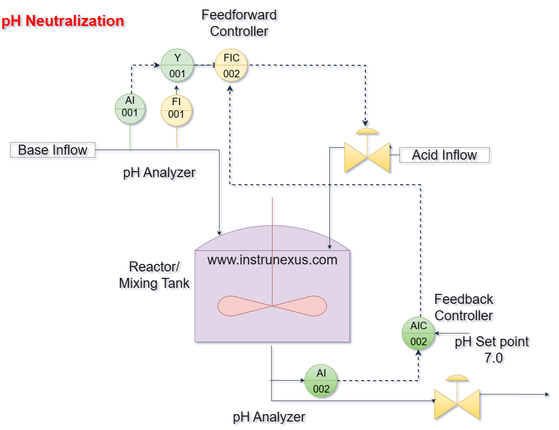
This diagram illustrates a combined feedforward-feedback control strategy for a pH neutralization process. The objective is to maintain a constant, neutral pH (e.g., 7.0) in the neutralized effluent despite disturbances in the incoming acid flow.
Components:
Reactor/Mixing Tank: Where the acid inflow is mixed with the neutralizing base.
Acid Inflow: The primary process stream whose pH needs to be adjusted. This is the source of the main disturbance.
Inflow pH & Flow Sensor (Disturbance Sensor): This crucial sensor measures both the pH and the flow rate of the incoming acid. These are the disturbance variables that the feedforward controller will use to anticipate changes.
Neutralizing Base: The reagent (e.g., caustic soda) added to neutralize the acid.
Control Valve: Adjusts the flow rate of the neutralizing base, which is the manipulated variable.
Feedforward Controller (FFC): Receives signals from the Inflow pH & Flow Sensor. Based on its internal model of the neutralization reaction, it calculates the required flow rate of the neutralizing base to immediately counteract the acidity of the incoming acid.
Outlet pH Sensor: Measures the actual pH of the neutralized effluent after mixing. This is the process variable being controlled.
Comparator: Compares the measured outlet pH to the desired Setpoint (e.g., pH 7.0).
Error Signal: The difference between the setpoint and the measured outlet pH. This is the input to the feedback (PID) controller.
PID Controller: This is the feedback component. It processes the error signal and generates a control signal to eliminate any residual pH error.
Summing Junction: Combines the outputs from the Feedforward Controller and the PID Controller to produce the final Combined Control Signal that drives the Control Valve.
How it Works:
Feedforward Action: When there’s a change in the acid inflow (e.g., increased flow rate or higher acidity), the Inflow pH & Flow Sensor immediately detects this. The Feedforward Controller rapidly calculates how much more neutralizing base is needed to maintain a neutral pH. It then sends a pre-emptive signal to the Control Valve to adjust the flow of neutralizing base. This action occurs before the acidic inflow has significantly altered the pH in the main mixing tank or reached the outlet sensor, thus proactively mitigating the disturbance.
Feedback Trim: Due to unmeasured disturbances (e.g., variations in reagent concentration, temperature effects) or inaccuracies in the feedforward model, perfect neutralization by feedforward alone is unlikely. The Outlet pH Sensor continuously monitors the actual pH of the effluent. If there’s any deviation from the pH 7.0 Setpoint, the Comparator generates an Error Signal. The PID Controller processes this error and provides a corrective signal to the Summing Junction, “trimming” the overall control signal to ensure precise pH control.
Benefits: pH control is notoriously difficult due to the highly non-linear nature of neutralization curves. A combined feedforward-feedback approach is particularly beneficial here. The feedforward rapidly handles the bulk of the neutralization based on known inflow conditions, preventing large pH swings. The feedback then provides the fine-tuning necessary to achieve and maintain the exact desired pH, leading to highly stable and accurate pH control, which is critical in environmental regulations, chemical production, and biological processes.
3. Boiler Control: Maintaining Steam Pressure
Scenario: Maintaining a stable steam pressure in a boiler, despite fluctuating demand for steam.
Disturbance: Steam demand (measured by steam flow rate).
Feedforward Action: A sensor measures the steam flow rate leaving the boiler. If steam demand suddenly increases, the feedforward controller immediately increases the fuel flow to the burners and/or the airflow to the combustion chamber. This pre-emptive action ensures that more heat is generated to produce more steam, preventing a drop in boiler pressure before it significantly occurs.
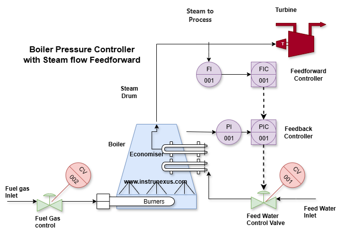
Components:
Boiler: The main unit where feedwater is heated to produce steam.
Feedwater In: The water supply to the boiler.
Fuel Supply & Air Supply: These are the manipulated variables, controlled by valves/dampers to regulate the combustion and heat generation.
Steam to Process: The outlet steam, which is consumed by various industrial processes.
Steam Flow Sensor (Disturbance Sensor): This critical sensor measures the rate at which steam is leaving the boiler. This is the disturbance variable that the feedforward controller will anticipate, as changes in steam flow directly represent changes in steam demand.
Feedforward Controller (FFC): Receives the signal from the Steam Flow Sensor. Based on its internal model (how much fuel/air is needed to generate a certain amount of steam), it calculates the immediate adjustment required for the fuel and/or air supply.
Boiler Pressure Sensor: Measures the actual steam pressure inside the boiler. This is the process variable being controlled.
Comparator: Compares the measured boiler pressure to the desired Boiler Pressure Setpoint (e.g., 100 psi).
Error Signal: The difference between the setpoint and the measured boiler pressure. This is the input to the feedback (PID) controller.
PID Controller: This is the feedback component. It processes the error signal and generates a control signal to eliminate any residual pressure error.
Summing Junction: Combines the outputs from the Feedforward Controller and the PID Controller to produce the final Combined Control Signal that drives the Fuel Supply and Air Supply actuators.
How it Works:
Feedforward Action: When there’s an increase in steam demand from the process, the Steam Flow Sensor immediately detects this. The Feedforward Controller then rapidly calculates how much more fuel and air are needed to meet this increased demand. It sends a pre-emptive signal to the Fuel Supply and Air Supply actuators to open further, increasing combustion and heat generation. This action occurs before the increased steam withdrawal has caused a significant drop in boiler pressure, thus proactively maintaining pressure.
Feedback Trim: Despite the feedforward action, there might be small deviations in boiler pressure due to unmeasured disturbances (e.g., changes in feedwater temperature, variations in fuel quality) or inaccuracies in the feedforward model. The Boiler Pressure Sensor continuously monitors the actual pressure. If there’s any deviation from the 100 psi Setpoint, the Comparator generates an Error Signal. The PID Controller processes this error and provides a corrective signal to the Summing Junction, “trimming” the overall control signal to ensure precise pressure control.
Benefits: Maintaining stable boiler pressure is crucial for safe and efficient operation and for providing consistent steam quality to downstream processes. A pure feedback system would react only after a pressure drop has occurred, leading to fluctuations. The combined feedforward-feedback strategy allows for rapid, proactive compensation for changes in steam demand (the primary disturbance), while the feedback loop ensures precise and robust control against any remaining errors, leading to significantly smoother boiler operation.
4. Distillation Column: Composition Control
Scenario: Maintaining a specific composition of product streams from a distillation column, despite variations in feed composition or flow rate.
Disturbance: Feed flow rate or feed composition to the distillation column.
Feedforward Action: Sensors measure the feed flow rate and/or the concentration of key components in the feed stream. If the concentration of a heavy component in the feed increases, the feedforward controller can immediately adjust the reboiler heat duty or reflux ratio to maintain the desired product purity, preventing the off-spec product before it’s even produced.
Distillation columns are complex processes with significant dead times and interactions, making them ideal candidates for feedforward control.
Scenario: Maintaining a specific composition of product streams (e.g., purity of the overhead product or bottom product) from a distillation column, despite variations in feed composition or flow rate.
Disturbances:
Feed Flow Rate: Changes in the total amount of material entering the column.
Feed Composition: Variations in the ratio of components (e.g., light key to heavy key) in the incoming feed stream.
Controlled Variables:
Overhead product composition (e.g., purity of the desired light component).
Bottom product composition (e.g., purity of the desired heavy component).
Manipulated Variables:
Reboiler heat duty (energy input to vaporize liquid at the bottom).
Reflux ratio (amount of condensed vapor returned to the column).
Feedforward Action:
Measure Disturbances:
Feed Flow Sensor: Measures the flow rate of the material entering the column.
Feed Composition Analyzer: Measures the concentration of key components (e.g., a gas chromatograph) in the incoming feed stream. This is crucial for anticipating compositional changes.
Calculate Compensation:
If the feed flow rate suddenly increases, the feedforward controller, using its internal model of the column, will immediately calculate the required increase in reboiler heat duty and/or reflux flow to process the additional material and maintain the desired product purities.
If the concentration of a heavier component in the feed increases, the feedforward controller will proactively adjust the reboiler heat duty (to provide more separation power) or the reflux ratio (to enhance separation in the rectification section) before the off-spec material reaches the product outlets.
Apply Compensation: The calculated adjustments are sent to the reboiler control valve (for steam/heating fluid) and the reflux pump/valve, taking pre-emptive action.
Combined with Feedback:
Product Composition Analyzers: Sensors at the overhead and/or bottom product streams continuously measure the actual composition.
Feedback PID Controllers: These controllers compare the measured product compositions to their respective setpoints. Any residual errors (due to unmeasured disturbances, model inaccuracies, or aging equipment) are then corrected by the feedback loop, fine-tuning the reboiler heat and reflux to achieve ultimate precision.
Benefits: Without feedforward, a change in feed conditions would propagate through the column, causing a significant delay (dead time) before the product composition sensors detect an error. By then, a substantial amount of off-spec product might have been produced. Feedforward control drastically reduces this “off-spec” time, leading to:
More consistent product quality.
Reduced product reprocessing.
Higher process efficiency and yield.
Smoother column operation, reducing oscillations.
One Response