Required Vessel & Process Parameters
Before starting the calculation, gather the following dimensions from the vessel’s general arrangement (GA) drawing:
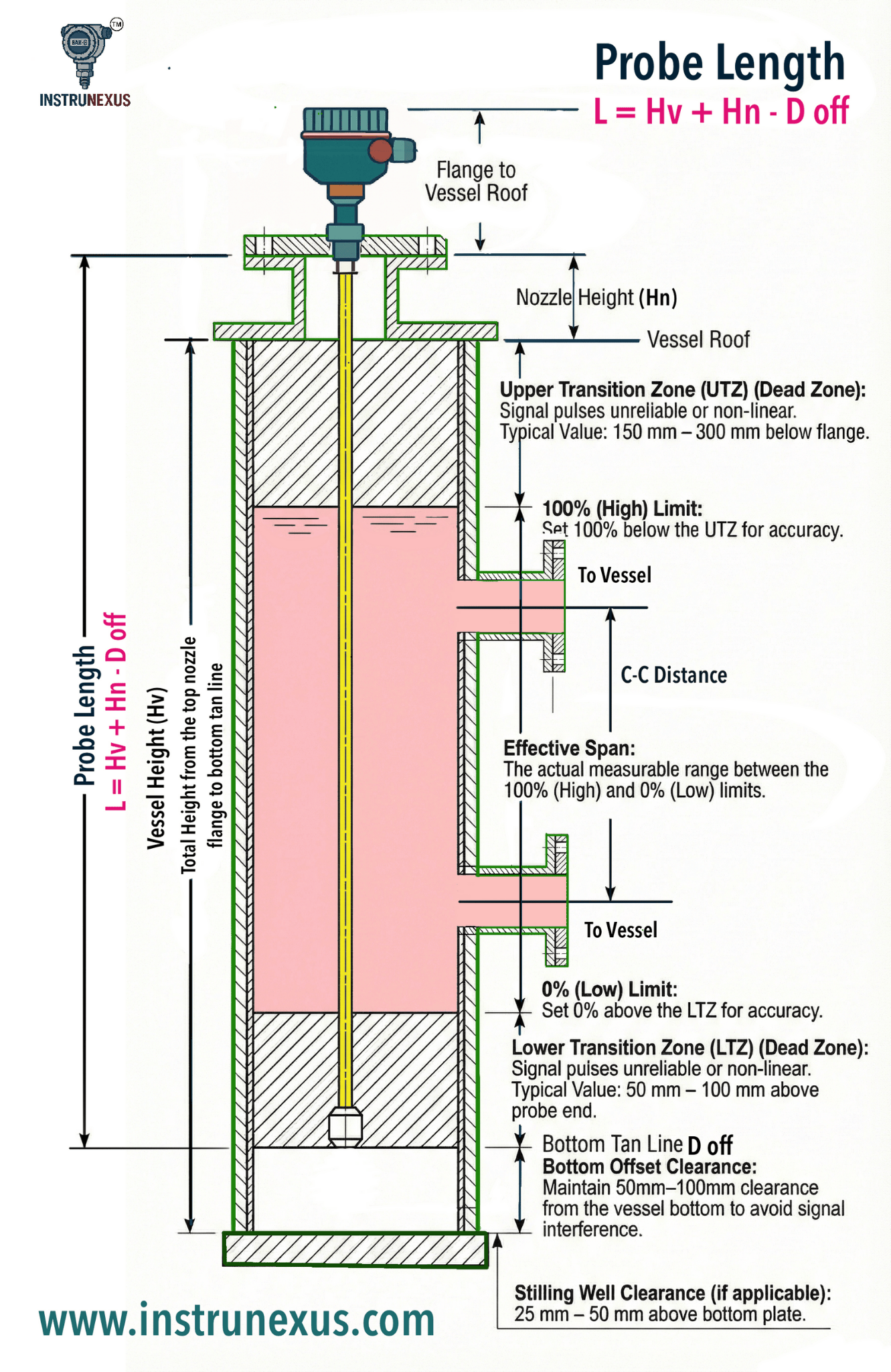
Vessel Height (): Total height from the top nozzle flange to the bottom tan line.
Nozzle Height (): The distance from the top of the process connection flange to the vessel roof.
High Level Limit (100%): The maximum desired liquid level (usually below the nozzle to avoid flooding).
Low Level Limit (0%): The minimum measurable level (typically above the bottom of the probe).
Stilling Well / Coaxial Details: The inner diameter of the pipe if the probe is installed in a chamber.
 How to calculate Guided Wave Radar (GWR) Probe length
2. Calculation Formula for Probe Length ()
The probe length is measured from the bottom of the process connection (flange face) to the very end of the probe.
- L = Hv + Hn − doff
Where is the Bottom Offset. To ensure the probe does not touch the bottom of the vessel (which could cause mechanical damage or signal interference), a clearance is required:
For Metallic Vessels: Maintain a clearance of 50 mm to 100 mm from the vessel bottom.
For Stilling Wells: If the probe is in a pipe, ensure the end is at least 25 mm to 50 mm above any reduction or bottom plate.
3. Defining the Measurement Span
The GWR cannot measure the full length of the probe due to Transition Zones (Dead Zones) at the top and bottom.
Upper Transition Zone (UTZ)
The area near the top of the probe where the signal is unreliable.
The High Level Limit (100%) should be set below the UTZ.
Typically, the 100% mark is 150 mm to 300 mm below the flange face.
Lower Transition Zone (LTZ)
The area at the bottom where the signal becomes non-linear as it nears the probe end.
The Low Level Limit (0%) should be set above the LTZ.
Typically, the 0% mark is 50 mm to 100 mm above the end of the probe.
4. Stilling Well Considerations
If installing in a Stilling Well or External Cage, the probe length should ideally match the full length of the chamber.
Venting: Ensure there is a vent hole in the stilling well within the Upper Transition Zone to allow gas equalization.
Centering: For long probes in stilling wells, use Centering Protectors (spacers) every 2–3 meters to prevent the probe from touching the pipe wall, which would cause a “false level” reflection.