Whether it’s refining crude oil, manufacturing life-saving pharmaceuticals, generating electricity, or purifying our drinking water, the ability to meticulously control the flow of fluids is a fundamental requirement. This is where the unsung hero of process control systems comes into play: the control valve. This comprehensive guide will demystify the workings of control valves, exploring their core components, diverse types, and critical role in ensuring the efficiency, safety, and reliability of modern industry.
What is a Control Valve and Why is it so Important?
At its core, a control valve is a power-operated device designed to modulate the flow of a fluid, such as a liquid, gas, or slurry, in a pipeline. Unlike a simple on/off valve, a control valve can operate at any position between fully open and fully closed, allowing for precise regulation of the flow rate, pressure, temperature, or liquid level. This capability makes it an essential final control element in a process control loop.
Imagine a simple scenario: maintaining a specific temperature in a chemical reactor. A temperature sensor measures the current temperature and sends this information to a controller. The controller compares the measured temperature to the desired setpoint and calculates the necessary adjustment. It then sends a signal to the control valve on the steam line feeding the reactor’s heating jacket. If the reactor is too cold, the control valve opens further to allow more steam; if it’s too hot, it closes slightly to reduce the steam flow. This continuous feedback and adjustment loop ensures the reactor operates at the optimal temperature.
Without effective control valves, industrial processes would be unpredictable, inefficient, and potentially hazardous. They are the hands that execute the decisions of the brain (the controller), ensuring everything runs smoothly and within safe limits.
Anatomy of a Control Valve: A Look Inside
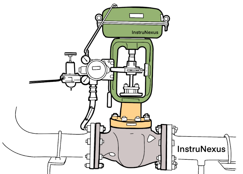
To understand how a control valve operates, it’s essential to familiarize ourselves with its key components. While designs vary, most control valves consist of three main parts: the valve body, the bonnet, and the actuator. The internal components responsible for controlling the flow are collectively known as the trim.
Blog Diagram: Anatomy of a Control Valve
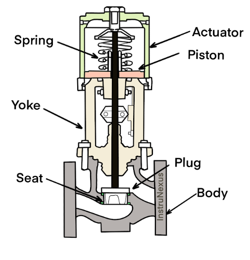
Valve Body: The valve body is the main pressure-containing structure of the valve. It houses the internal components that come into contact with the fluid and forms the primary boundary for the process fluid. It has an inlet and an outlet port through which the fluid enters and exits.
Bonnet: The bonnet is the cover for the opening in the valve body. It is bolted or screwed onto the body and provides a leak-proof closure. The bonnet also houses the packing box and supports the actuator.
Trim: The trim is the heart of the control valve and includes the components that are in direct contact with the fluid and are responsible for the flow modulation. The primary parts of the trim are:
- Stem: A rod that connects the actuator to the plug, transmitting the force from the actuator to control the plug’s movement.
- Plug (or Disc): The movable part of the valve that is positioned in the flow path to control the flow rate. The shape of the plug is crucial as it determines the valve’s flow characteristic.
- Seat: A stationary ring in the valve body against which the plug rests in the closed position to provide a tight shut-off.
Actuator: The actuator is the powerhouse of the control valve. It is a device that converts an energy source into the mechanical motion required to move the valve’s trim. The type of energy used can be pneumatic (compressed air), electric, or hydraulic. The actuator responds to the control signal from the controller, adjusting the position of the stem and plug accordingly.
Positioner: Often working in conjunction with the actuator, a positioner is a device that ensures the valve reaches the exact position dictated by the control signal. It compares the control signal with the actual position of the valve stem and adjusts the actuator’s power source until the desired position is achieved, overcoming any friction or process-induced forces.
The Process Control Loop: A Symphony of Components
The control valve never works in isolation. It is a key player in a larger system known as a process control loop. Understanding this loop is fundamental to grasping the significance of the control valve.
Blog Diagram: The Process Control Loop
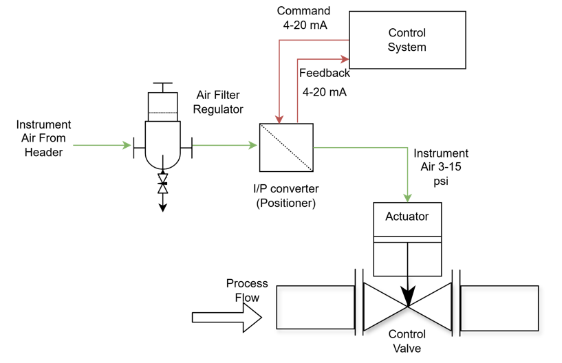
The process control loop consists of four essential elements:
- The Process: This is the system being controlled, such as a tank, a pipeline, or a reactor, with a specific variable that needs to be maintained (e.g., level, temperature, pressure, or flow).
- The Sensor/Transmitter: A sensor measures the process variable (e.g., a pressure gauge or a temperature probe). A transmitter then converts this measurement into a standardized electrical or pneumatic signal.
- The Controller: This is the “brain” of the loop. It can be a standalone device or part of a larger distributed control system (DCS) or programmable logic controller (PLC). The controller receives the signal from the transmitter, compares it to the desired setpoint, and determines the necessary corrective action.
- The Final Control Element (The Control Valve): The controller sends a signal to the actuator of the control valve, which then adjusts the valve’s opening to manipulate the flow of a fluid (the manipulated variable) to bring the process variable back to the setpoint.
This continuous cycle of measuring, comparing, calculating, and acting allows for the precise and automatic control of industrial processes.
Types of Control Valves: The Right Tool for the Job
Control valves come in a wide variety of designs, each with its own set of advantages and disadvantages, making them suitable for different applications. The most common types include:
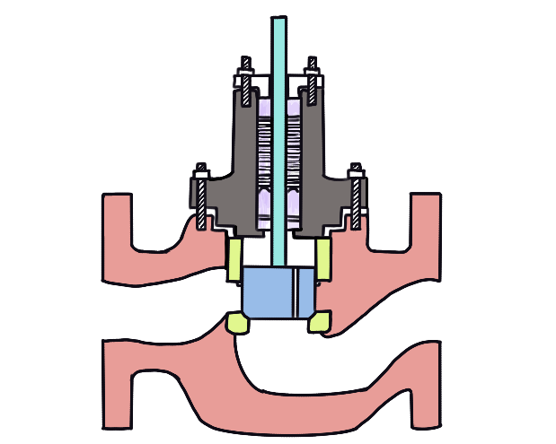
Globe Valves
Globe valves are one of the most common types of control valves used for throttling and precise flow control. Their internal design, featuring a Z-shaped or S-shaped flow path, forces the fluid to change direction, which, while creating a pressure drop, allows for very fine control over the flow rate.
- Advantages: Excellent throttling and shut-off capabilities, high accuracy for flow control.
- Disadvantages: Higher pressure drop compared to other valve types, which can lead to lower energy efficiency. They are also generally more expensive and physically larger.
- Common Applications: Cooling water systems, fuel oil systems, and applications requiring precise temperature or pressure control.
Ball Valves
Ball valves are quarter-turn rotary valves that use a spherical-shaped closure element with a bore through it. When the valve is open, the bore is aligned with the pipeline, allowing for unrestricted flow. A 90-degree turn of the actuator positions the solid part of the ball against the flow, shutting it off.
Blog Diagram: Inside a Ball Valve
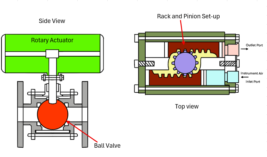
- Advantages: High flow capacity with low pressure drop, excellent shut-off capabilities, and a compact and lightweight design.
- Disadvantages: Traditional ball valves are not ideal for precise throttling as the flow characteristic is not as fine as that of a globe valve. However, segmented ball valves offer improved throttling performance.
- Common Applications: On/off isolation services, and with segmented designs, they are used in slurry and pulp applications.
Butterfly Valves
Butterfly valves are another type of quarter-turn rotary valve. They feature a circular disc mounted on a central stem. In the closed position, the disc is perpendicular to the flow, blocking it. A quarter-turn of the stem rotates the disc parallel to the flow, allowing the fluid to pass.
Blog Diagram: Inside a Butterfly Valve

- Advantages: Lightweight, compact, lower cost, and high flow capacity.
- Disadvantages: Can have a higher leakage rate compared to globe or ball valves, and the disc is always present in the flow path, causing a slight pressure drop even when fully open.
- Common Applications: Large-diameter pipelines for water and gas distribution, HVAC systems, and applications where a tight shut-off is not the primary requirement.
Understanding Flow Characteristics: How a Valve Behaves
The relationship between the valve’s opening and the flow rate through it is known as its flow characteristic. This is a critical factor in selecting the right valve for a particular application to ensure stable and responsive control. The two most common inherent flow characteristics are:
Linear: In a valve with a linear flow characteristic, the flow rate is directly proportional to the valve travel. For example, at 50% open, the flow rate is 50% of the maximum flow. This type of characteristic is typically used in applications where the pressure drop across the valve remains relatively constant.
Equal Percentage: For an equal percentage valve, each equal increment of valve travel produces an equal percentage change in the existing flow rate. This means that a small change in valve position at low openings results in a small change in flow, while the same change in position at larger openings results in a much larger change in flow. This characteristic is ideal for applications where the pressure drop across the valve varies significantly with the flow rate, as it helps to linearize the overall system response.
Blog Diagram: Flow Characteristics Graph

Real-World Applications of Control Valves
Control valves are ubiquitous in a vast array of industries, performing critical functions that keep our modern world running.
Oil and Gas: In the oil and gas industry, control valves are used to manage the flow of crude oil, natural gas, and refined products through pipelines, separators, and processing units. They are essential for pressure regulation, level control in storage tanks, and temperature control in heaters and coolers.
Chemical Processing: The chemical industry relies heavily on control valves for the precise mixing of reactants, maintaining reactor temperatures and pressures, and controlling the flow of various corrosive and hazardous chemicals. The accuracy of control valves directly impacts product quality and process safety.
<b>Power Generation:</b> In power plants, control valves are critical for regulating the flow of steam to turbines, controlling the feedwater to boilers, and managing cooling water systems. Their performance is directly linked to the efficiency and safety of power generation.
Water and Wastewater Treatment: Control valves play a vital role in water treatment plants by regulating the flow of water through various filtration and chemical treatment processes. They are also used to control the flow of sludge and other materials in wastewater treatment facilities.
Conclusion: The Unseen Force of Industrial Automation
Control valves are the workhorses of process control systems, tirelessly and precisely manipulating fluid flow to maintain stability, ensure quality, and protect valuable equipment and personnel. From the intricate network of pipes in a chemical plant to the massive infrastructure of a power station, these remarkable devices are the final, crucial link in the chain of automated control. By understanding the fundamental principles of how control valves work, their various types, and their role within the broader context of a process control loop, we gain a deeper appreciation for the elegant engineering that underpins our modern industrial world. The next time you turn on a light, use a plastic product, or drink clean water, remember the silent, yet powerful, contribution of the humble control valve.