
How DP Transmitters Master Interface Level Measurement in Separators
In the intricate world of industrial processing, the precise measurement and control of fluid levels within separators are paramount. These vessels, critical for separating immiscible fluids like oil and water, rely on accurate interface level detection to ensure product quality, prevent costly contamination, and maintain operational safety. While various technologies exist for this purpose, the differential pressure (DP) transmitter remains a stalwart and widely adopted solution. This in-depth blog post will demystify the principles behind how DP transmitters flawlessly measure interface level in separators, delving into the science, calculations, installation nuances, and best practices that underpin this essential industrial application.
The Fundamental Principle: Harnessing Hydrostatic Pressure
At its core, the ability of a DP transmitter to measure an interface level is rooted in the fundamental principle of hydrostatic pressure. This principle states that the pressure exerted by a column of fluid at rest is directly proportional to its height, density (or specific gravity), and the acceleration due to gravity. A DP transmitter, as its name suggests, measures the difference in pressure between two distinct points. By strategically placing these two pressure taps on a separator, we can ingeniously use this pressure differential to infer the location of the interface between two liquids of differing densities.
To comprehend this, let’s visualize a typical separator containing two immiscible liquids, for instance, oil and water. Water, being denser, will settle at the bottom, while the lighter oil will form a layer on top. A DP transmitter is installed with its high-pressure (HP) port connected to a lower nozzle on the vessel and its low-pressure (LP) port connected to a higher nozzle.
The pressure sensed at the HP port is the sum of the hydrostatic pressure exerted by the column of the heavier liquid (water) and the column of the lighter liquid (oil) above it, in addition to any gas pressure at the top of the separator. The pressure at the LP port is influenced by the hydrostatic pressure of the lighter liquid and the same gas pressure. The DP transmitter continuously calculates the difference between these two pressures. As the interface level between the oil and water changes, the proportional heights of the two liquid columns between the taps change, resulting in a corresponding change in the differential pressure. This change is then calibrated to represent the interface level, typically as a percentage or a specific engineering unit.
The Critical Role of Specific Gravity
The accuracy of interface level measurement using a DP transmitter is inextricably linked to the specific gravity (SG) of the two liquids. Specific gravity is the ratio of a liquid’s density to the density of a reference substance, usually water. Since the hydrostatic pressure is directly proportional to the fluid’s density, a stable and known specific gravity for each liquid is crucial for accurate calibration and measurement.
Any fluctuation in the specific gravity of either liquid will directly impact the hydrostatic pressure they exert, leading to an erroneous interface level reading. Therefore, in applications where the specific gravity of the process fluids is known to vary significantly with temperature or composition, this method may require compensation techniques or alternative measurement technologies might be more suitable.
Setting the Stage: Installation and Calibration
The proper installation and meticulous calibration of the DP transmitter are non-negotiable for achieving reliable interface level measurement. There are two primary installation methods: one utilizing a wet leg and the other employing remote seals.
Installation Methods: Wet Leg vs. Remote Seals
A wet leg installation involves filling the impulse piping connecting the low-pressure side of the transmitter to the upper tap with a reference fluid of known and constant specific gravity. This creates a constant hydrostatic head on the LP side, providing a stable reference pressure. However, wet legs can be susceptible to evaporation, contamination, or temperature-induced density changes of the fill fluid, which can introduce errors.
A more robust and increasingly popular alternative is the use of remote seals. A remote seal system consists of a diaphragm seal connected to the transmitter via a capillary tube filled with a non-compressible fluid. This setup isolates the transmitter from the process fluid, making it ideal for corrosive, high-temperature, or viscous applications. The use of remote seals eliminates the potential issues associated with wet legs, offering a more stable and maintenance-friendly solution.
The Art of Calibration: Setting the Lower and Upper Range Values (LRV and URV)
The calibration of a DP transmitter for interface level measurement involves establishing a relationship between the measured differential pressure and the actual interface level. This is achieved by calculating and setting the Lower Range Value (LRV) and the Upper Range Value (URV), which correspond to 0% and 100% of the desired interface level measurement span, respectively.
The calculation of LRV and URV is a critical step that requires precise knowledge of the specific gravities of the two liquids and the vertical distance between the HP and LP taps.
Let’s consider a practical example:
H: Distance between the HP and LP taps = 100 inches
SG1: Specific gravity of the heavier liquid (water) = 1.0
SG2: Specific gravity of the lighter liquid (oil) = 0.85
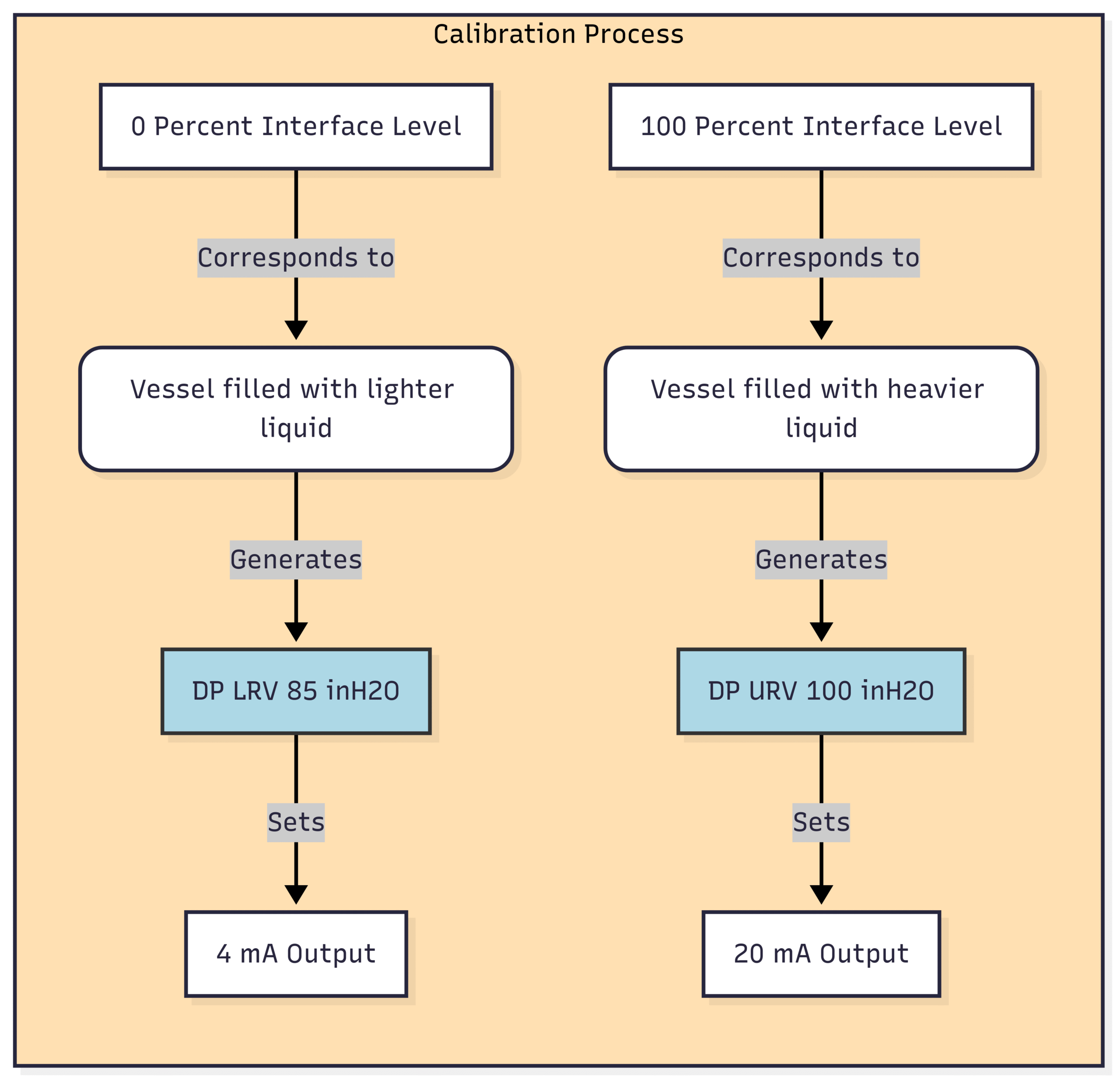
Calculating the Lower Range Value (LRV – 0% Interface Level):
The 0% interface level typically corresponds to the vessel being filled only with the lighter liquid up to the level of the upper tap.
Pressure at HP tap () = (H * SG2) = 100 inches * 0.85 = 85 inches of water column ()
Pressure at LP tap () = 0 (assuming the LP tap is at the reference point)
Differential Pressure (DP) at 0% = – = 85 Therefore, LRV = 85 . This differential pressure will correspond to a 4 mA output from the transmitter.
Calculating the Upper Range Value (URV – 100% Interface Level):
The 100% interface level corresponds to the vessel being filled with the heavier liquid up to the level of the upper tap.
Pressure at HP tap () = (H * SG1) = 100 inches * 1.0 = 100
Pressure at LP tap () = 0
Differential Pressure (DP) at 100% = – = 100 Therefore, URV = 100 . This differential pressure will correspond to a 20 mA output from the transmitter.
The calibrated span of the transmitter would then be from 85 to 100 . Any differential pressure reading between these values will be linearly interpreted by the control system as the interface level.
Real-World Applications and Potential Challenges
DP transmitters find widespread application for interface level measurement across various industries, including:
Oil and Gas Production: In separators to distinguish between crude oil, water, and gas.
Refining: In desalters and other vessels to separate hydrocarbons from water and other impurities.
Chemical Processing: In reactors and settlers where immiscible liquids need to be separated.
Wastewater Treatment: To monitor the interface between oil and water in separators before discharge.
Despite their versatility, using DP transmitters for interface level measurement is not without its challenges:
Emulsions and Rag Layers: The formation of an emulsion or a “rag layer” (a mixture of the two liquids and solids) at the interface can create a density gradient rather than a sharp interface. This can lead to inaccuracies in the measurement as the DP transmitter assumes a distinct interface.
Density Variations: As mentioned earlier, changes in process temperature or composition can alter the specific gravities of the liquids, leading to measurement errors.
Build-up and Clogging: Process fluids can sometimes cause build-up on the diaphragm seals or clog the impulse piping, affecting the pressure transmission and leading to erroneous readings. Regular maintenance and flushing are crucial to mitigate this.
Vapor Phase Density: In high-pressure applications, the density of the vapor phase may become significant and can influence the differential pressure measurement if not accounted for in the calibration.
Troubleshooting Common Issues DP transmitter for Interface level measurement
When faced with an inaccurate or unreliable interface level reading from a DP transmitter, a systematic troubleshooting approach is key. Here are some common issues and their potential solutions:
Advantages and Disadvantages of Using DP Transmitters for Interface Level
Like any technology, DP transmitters offer a unique set of advantages and disadvantages for interface level measurement.
Advantages:
Cost-Effective: DP transmitters are generally a more economical solution compared to some other advanced level measurement technologies.
Proven and Reliable: The technology is well-established and has a long track record of reliable performance in various industrial applications.
Versatility: They can be used with a wide range of liquids and in various process conditions.
External Mounting: The transmitter is mounted externally, allowing for easier maintenance and calibration without shutting down the process.
Disadvantages:
Sensitivity to Density Changes: The accuracy is highly dependent on the constant specific gravities of the liquids.
Not Ideal for Emulsions: The presence of a significant rag layer can lead to inaccurate readings.
Requires Two Vessel Connections: This can increase the potential for leaks and adds to the installation complexity.
Impulse Line Maintenance: Wet legs and impulse piping can require periodic maintenance to prevent clogging and ensure accuracy.
Conclusion: A Time-Tested and Trusted Method
In the demanding environment of industrial separators, the humble DP transmitter continues to prove its mettle as a reliable and cost-effective tool for interface level measurement. By cleverly leveraging the fundamental principles of hydrostatic pressure and with careful attention to installation, calibration, and maintenance, this versatile instrument provides the critical data needed for efficient and safe process control. While newer technologies offer alternatives, the simplicity, robustness, and deep-rooted understanding of DP transmitter-based interface measurement ensure its enduring place in the industrial instrumentation toolkit. Understanding its principles of operation, its strengths, and its limitations is key to successfully applying this technology and unlocking its full potential in ensuring the smooth and efficient operation of separation processes.