An imperative in the high-stakes world of industrial processing is the uncompromising pursuit of safety. When processes involve hazardous materials or extreme conditions, the consequences of failure can be catastrophic. This is where the concept of Safety Integrity Level (SIL) emerges as a cornerstone of modern risk management. A SIL rating quantifies the necessary risk reduction a safety function must provide. But how can you be certain that your safety systems are as robust as they need to be? The answer lies in a meticulous and systematic process known as SIL verification.
This comprehensive guide will walk you through the intricacies of performing a SIL verification step-by-step. We will delve into the fundamental concepts, demystify the calculations, and provide a clear roadmap for ensuring your safety instrumented systems (SIS) meet their designated safety targets. By the end of this blog, you will have a thorough understanding of the methodologies prescribed by international standards like IEC 61508 and IEC 61511, empowering you to approach SIL verification with confidence.
Part 1: Understanding the Fundamentals
Before embarking on the step-by-step verification process, it’s crucial to grasp the foundational concepts that underpin SIL.
What is SIL?
At its core, a Safety Integrity Level (SIL) is a measure of the reliability of a Safety Instrumented Function (SIF). It represents the degree of risk reduction that a particular safety function provides. There are four discrete SIL levels, from SIL 1 to SIL 4. A higher SIL level corresponds to a greater degree of risk reduction and, consequently, a more reliable safety function.
The reliability of a SIF is quantified by its Probability of Failure on Demand (PFDavg) for systems that operate in low-demand mode, or its Probability of Failure per Hour (PFH) for systems in high-demand or continuous mode. The following table illustrates the relationship between SIL, the required Risk Reduction Factor (RRF), and the target PFDavg and PFH values:
SIL Determination vs. SIL Verification vs. SIL Validation
It is essential to distinguish between three distinct yet interconnected stages of the safety lifecycle:
SIL Determination (or SIL Assessment): This is the initial phase where the required SIL for a specific safety function is determined. This is typically achieved through process hazard analyses (PHAs) like Hazard and Operability studies (HAZOPs) and Layer of Protection Analysis (LOPA). The goal is to identify the necessary risk reduction to bring the process to a tolerable risk level.
SIL Verification: This is the analytical part of the process, performed during the design phase. It involves calculating the performance of the designed SIF to ensure it meets the target SIL determined in the previous step. This is a predictive analysis based on the chosen components and system architecture.
SIL Validation: This is the final “as-built” check. It involves testing the installed and commissioned SIS to confirm that it operates as specified in the safety requirements specification and meets the assigned SIL.
A simple analogy can be drawn to building a bridge: SIL determination is deciding the bridge needs to support 20 tons of traffic. SIL verification is the engineering calculation that proves the bridge’s design, materials, and construction plans will indeed support 20 tons. SIL validation is the physical load testing of the completed bridge to confirm it can handle the 20-ton load.
The Anatomy of a Safety Instrumented Function (SIF)
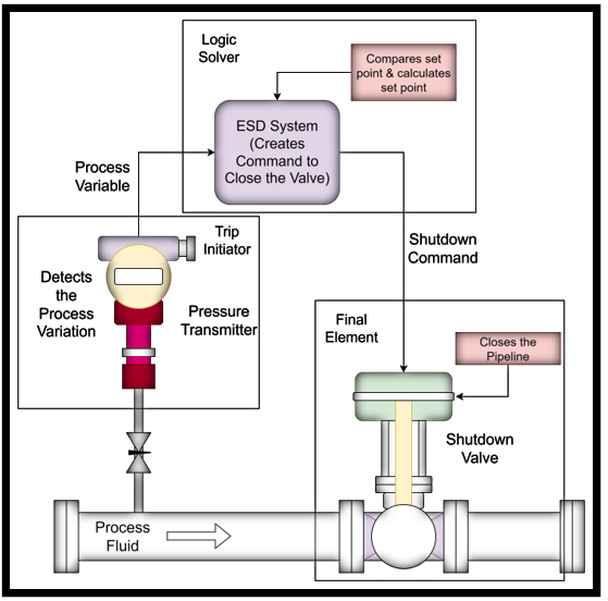
A SIF is a specific safety function designed to bring a process to a safe state. It is comprised of three fundamental types of components working in unison:
Sensor(s): These are the “eyes” of the SIF, responsible for detecting a hazardous condition. Examples include pressure transmitters, level switches, and gas detectors.
Logic Solver(s): This is the “brain” of the SIF. It processes the input from the sensor(s) and, based on its programmed logic, decides whether to initiate a protective action. This can be a dedicated safety PLC or, in simpler applications, relays.
Final Element(s): These are the “hands” of the SIF that carry out the protective action. Common final elements include emergency shutdown valves (ESVs), trip relays, and motor starters that shut down pumps or compressors.
Block Diagram 1: The Generic SIF Loop
Part 2: The SIL Verification Process: A Step-by-Step Guide
With the fundamentals in place, let’s embark on the detailed, step-by-step process of performing a SIL verification.
Step 1: Define the Safety Instrumented Function (SIF)
The first and arguably most crucial step is to have a crystal-clear and unambiguous definition of the SIF. A poorly defined SIF will lead to an inaccurate verification. The SIF definition should include:
The Hazard: What specific hazard is the SIF protecting against (e.g., high pressure in a reactor, overfilling of a storage tank)?
The Action: What action must the SIF take to mitigate the hazard (e.g., close the inlet valve, trip the feed pump)?
The Safe State: What is the resulting safe state of the process after the SIF has acted?
The Trip Point: At what process value should the SIF be activated?
Response Time: How quickly must the SIF act to prevent the hazardous event?
Step 2: Identify All Components in the SIF Loop
Every component that contributes to the execution of the SIF must be identified and included in the verification. This includes not only the main sensors, logic solvers, and final elements but also all auxiliary components such as:
Power supplies
Relays and interposing relays
Solenoid valves
Tubing and impulse lines
Manual valves that are part of the SIF
A failure of any of these components could lead to a failure of the SIF as a whole.
Step 3: Gather the Reliability Data
Accurate and reliable data is the lifeblood of a credible SIL verification. For each component identified in Step 2, you will need to gather specific failure rate data. The primary sources for this data are:
Manufacturer’s Certificates: Reputable manufacturers of safety-rated devices provide certificates from accredited bodies like exida or TÜV. These certificates contain the necessary failure rate data determined through a rigorous Failure Modes, Effects, and Diagnostics Analysis (FMEDA).
Industry Databases: Organizations like the Offshore and Onshore Reliability Data (OREDA) project compile historical failure data from various industries.
User-Specific Data: If a company has a robust maintenance and data collection system, its own historical data on component performance can be a valuable source.
The key data points you will need for each component are:
Dangerous Undetected (λdu) Failure Rate: The rate at which a component fails in a way that is dangerous (i.e., prevents the SIF from working) and is not detected by any automatic diagnostics. This is the most critical parameter for PFDavg calculations.
Dangerous Detected (λdd) Failure Rate: The rate of dangerous failures that are automatically detected by the system’s diagnostics.
Safe Failure Fraction (SFF): The percentage of all failures that are either safe or dangerous but detected.
Diagnostic Coverage (DC): The percentage of dangerous failures that are detected by automatic diagnostics.
Proof Test Coverage (PTC): The percentage of dangerous undetected failures that can be identified during a periodic proof test.
Mean Time To Repair (MTTR): The average time it takes to repair a failed component once it has been detected.
Step 4: The Three Barriers to SIL Achievement
As stipulated by the IEC standards, achieving a target SIL is not just about a single calculation. A SIF’s design must overcome three distinct “barriers” to be considered verified:
Probability of Failure (PFDavg/PFH): A quantitative assessment of the SIF’s reliability.
Architectural Constraints: Rules regarding the hardware fault tolerance and redundancy of the SIF.
Systematic Capability: Measures to prevent systematic failures (e.g., design errors, software bugs).
Block Diagram 2: The Three Barriers of SIL Verification

Step 5: Barrier 1 – Calculating the Probability of Failure
This step involves the mathematical calculation to determine if the SIF meets its target PFDavg (for low-demand mode) or PFH (for high-demand/continuous mode).
For a simple 1-out-of-1 (1oo1) architecture in low-demand mode, a simplified formula for PFDavg is:
Where:
is the dangerous undetected failure rate.
is the proof test interval (the time between full tests of the SIF).
For more complex architectures with redundancy, such as 1oo2 or 2oo3, the formulas become more complex and must account for factors like common cause failures. For instance, for a 1oo2 architecture, the PFDavg is influenced by both independent and common cause failures.
Given the complexity, especially for redundant systems, it is highly recommended to use specialized SIL verification software. These tools can handle complex architectures, incorporate various failure modes, and provide detailed and accurate calculations.
Step 6: Barrier 2 – Meeting Architectural Constraints
Architectural constraints are rules that limit the SIL that can be claimed for a SIF, regardless of the calculated PFDavg. These constraints ensure a minimum level of fault tolerance in the hardware. The key concept here is Hardware Fault Tolerance (HFT). An HFT of ‘N’ means that ‘N+1’ faults are required to cause a loss of the safety function.
IEC 61511 provides two routes for demonstrating compliance with architectural constraints:
Route 1H: This route is based on the SFF and HFT of the components. A table in the standard specifies the minimum HFT required for a given SIL level and component type (Type A – simple devices, or Type B – complex devices like PLCs).
Route 2H: This route is based on “proven-in-use” data, which demonstrates a component’s high reliability through extensive operational history.
A simplified example of HFT requirements from IEC 61511 for a SIL 2 SIF is an HFT of 0, meaning a single component failure is permissible. For a SIL 3 SIF, a minimum HFT of 1 is often required, necessitating redundancy.
Step 7: Barrier 3 – Addressing Systematic Capability (SC)
Systematic failures are inherent in the design, manufacturing, or operational procedures. They are not random hardware failures. Examples include:
Software bugs in a safety PLC.
Errors in the safety requirements specification.
Incorrect installation or maintenance procedures.
To address this, the concept of Systematic Capability (SC) is used. Components are certified for use up to a certain SIL level based on the rigor of the manufacturer’s design and development processes. A SIF cannot achieve a SIL level higher than the lowest SC rating of any of its components. Therefore, if you are designing a SIL 3 SIF, all components must have a systematic capability of at least SC 3.
Step 8: Accounting for Common Cause Failures (CCF)
In redundant architectures (e.g., 1oo2, 2oo3), there is a risk that a single event could cause multiple components to fail simultaneously. This is known as a Common Cause Failure (CCF). Examples of CCF include:
A plugged impulse line affecting redundant pressure transmitters.
Extreme environmental conditions (e.g., vibration, corrosion) affecting multiple identical devices.
A maintenance error that is repeated on all redundant components.
CCFs can negate the benefits of redundancy. The Beta-factor model is a common method for quantifying the impact of CCF. The beta factor (β) represents the fraction of total failures that are due to a common cause. To mitigate CCFs, designers can employ strategies like:
Diversity: Using different technologies or manufacturers for redundant components.
Physical Separation: Installing redundant components in different locations.
Staggered Testing: Not testing all redundant components at the same time.
Step 9: Compare and Document
The final step in the verification process is to bring everything together. You must compare the results of your analysis against the target SIL for the SIF:
Is the calculated PFDavg/PFH lower than the maximum allowed for the target SIL?
Does the SIF’s architecture meet the minimum HFT requirements for the target SIL?
Do all components have a systematic capability rating equal to or greater than the target SIL?
If the answer to all three questions is “yes,” then the SIF is considered verified. If not, the design must be revised and the verification process repeated. This may involve selecting more reliable components, increasing the proof test frequency, or adding redundancy.
All the steps, assumptions, data sources, calculations, and conclusions must be meticulously documented in a SIL Verification Report.
Part 3: The SIL Verification Report
The SIL verification report is the formal record of the entire process. It serves as evidence that the SIF design has been thoroughly evaluated and meets the required safety standards. A comprehensive report should include:
Introduction and Purpose: A brief overview of the SIF and the objective of the verification.
Detailed SIF Description: A clear explanation of the SIF’s functionality, including the hazard it protects against, its trip point, and the actions it takes.
Assumptions and Data Sources: A list of all assumptions made during the analysis and the sources of all reliability data used.
Calculation Results: The detailed calculations for the PFDavg or PFH of the SIF.
Architectural Constraint Analysis: A demonstration of how the SIF meets the required HFT.
Systematic Capability Assessment: Confirmation that all components meet the required SC rating.
Common Cause Failure Analysis: The methodology used to account for CCFs and the results.
Conclusion: A clear statement on whether the SIF has been successfully verified to meet the target SIL.
Recommendations: If the SIF fails verification, the report should provide specific recommendations for design modifications to achieve the target SIL.
Conclusion
Performing a SIL verification is an exacting but essential discipline in the world of process safety. It is a systematic journey that transforms a theoretical safety requirement into a robust and reliable design. By meticulously following the steps outlined in this guide – from defining the SIF to documenting the final results – you can ensure that your safety instrumented systems provide the level of protection that your people, your assets, and the environment demand.
Remember, SIL verification is not a one-time event. It is an iterative process that may require design refinements. It is a critical investment in safety that pays immeasurable dividends by preventing catastrophic failures and fostering a culture of operational excellence. By embracing the principles of SIL verification, you are not just complying with standards; you are making a steadfast commitment to a safer future.