IEC 61508 Part 2 and 3 – Hardware and Software Requirements Explained
In the world of industrial automation and safety-critical systems, ensuring that equipment operates safely and reliably is not just a matter of good practice; it’s a fundamental necessity. The international standard IEC 61508 provides a rigorous framework for the functional safety of electrical, electronic, and programmable electronic (E/E/PE) safety-related systems. It’s a comprehensive document, and for those new to it, navigating its various parts can be a daunting task. This blog post aims to demystify two of the most critical components of this standard: Part 2, which focuses on hardware requirements, and Part 3, which details software requirements.
This 2000-word guide will walk you through the core principles of each part, explaining the key concepts, methodologies, and their interplay in achieving the desired level of safety. We’ll explore the hardware safety lifecycle, the intricacies of architectural constraints, and the rigorous demands placed on software development, all illustrated with block diagrams to clarify these complex processes.
The Foundation: Understanding Functional Safety and IEC 61508
Before we delve into the specifics of hardware and software, let’s establish a foundational understanding of functional safety. In essence, functional safety is the part of the overall safety of a system or piece of equipment that depends on the correct functioning of its safety-related systems. These systems are designed to automatically prevent or mitigate the consequences of hazardous events.
IEC 61508 is the umbrella standard for functional safety. It establishes a systematic approach to the entire safety lifecycle, from initial concept and risk assessment to design, implementation, operation, and decommissioning. A core concept within IEC 61508 is the Safety Integrity Level (SIL), which is a measure of the risk reduction provided by a safety function. There are four SILs, from SIL 1 (lowest integrity) to SIL 4 (highest integrity). The required SIL for a particular safety function is determined through a thorough risk analysis of the process or system being controlled.
While Part 1 of the standard lays out the general requirements, Parts 2 and 3 provide the detailed “how-to” for hardware and software, respectively.
Part 2: Hardware Requirements
IEC 61508-2 sets forth the requirements for the hardware of E/E/PE safety-related systems. The primary goal is to ensure that the hardware is designed and implemented in a way that it can tolerate random hardware failures and that any failures that do occur are detected and lead to a safe state.
The Hardware Safety Lifecycle
The development of safety-critical hardware follows a structured lifecycle, which is a key tenet of IEC 61508. This lifecycle ensures that safety is considered at every stage of the development process, from conception to retirement.
Block Diagram Description: The Hardware Safety Lifecycle (IEC 61508-2)

Architectural Constraints: Building in Resilience
A cornerstone of hardware safety is the concept of architectural constraints. These are rules that dictate the required level of fault tolerance and the effectiveness of diagnostic measures within the hardware design. The two key metrics here are:
Hardware Fault Tolerance (HFT): This refers to the ability of a system to continue to perform its required function in the presence of one or more hardware faults. An HFT of ‘N’ means the system can tolerate ‘N’ faults and still operate safely. For example, a simple single-channel system has an HFT of 0. A dual-channel system where either channel can perform the safety function has an HFT of 1.
Safe Failure Fraction (SFF): This is a measure of the proportion of failures in a component that are either safe (i.e., they do not lead to a hazardous event) or are detected by diagnostic tests. A higher SFF indicates a more robust design where a larger percentage of potential failures are effectively managed. The formula for SFF is:
Where:
= Safe Detected failure rate
= Safe Undetected failure rate
= Dangerous Detected failure rate
= Dangerous Undetected failure rate
IEC 61508-2 provides tables that link the required HFT to the SFF and the target SIL. This ensures that for a given SIL, the hardware architecture has an appropriate level of redundancy and self-monitoring capabilities.
Routes to Compliance: 1H and 2H
IEC 61508-2 offers two primary “routes” for demonstrating the hardware’s compliance with the architectural constraints:
Route 1H: This is the primary route, based on a quantitative analysis of the hardware. It involves calculating the HFT and SFF for each element of the safety function. This route is typically used for new or complex devices where extensive field data is not available. A detailed Failure Mode and Effects and Diagnostics Analysis (FMEDA) is often employed to determine the failure rates and modes of the components, which are then used to calculate the SFF.
Route 2H: This route provides an alternative path to compliance based on proven-in-use data. If a component has a well-documented history of reliable operation in a similar environment and application, this data can be used to justify its use in a safety system. This route acknowledges that real-world performance is a powerful indicator of reliability. However, the quality and relevance of the data are strictly scrutinized.
The choice between Route 1H and 2H depends on the nature of the component, the availability of reliable field data, and the complexity of the system.
The Role of Diagnostic Coverage
Diagnostic Coverage (DC) is a crucial factor in achieving a high SFF. It represents the percentage of dangerous hardware failures that are detected by the system’s diagnostic tests. A high DC means that the system is very effective at identifying internal faults before they can lead to a hazardous situation. The diagnostic tests can range from simple power-on self-tests to continuous online monitoring of critical parameters.
Part 3: The Intangible Guardian – Software Requirements
While hardware failures are often random in nature, software failures are typically systematic. This means they are inherent in the design or implementation of the software and will manifest under specific conditions. IEC 61508-3 is dedicated to preventing these systematic failures in safety-related software.
The Software Safety Lifecycle and the V-Model
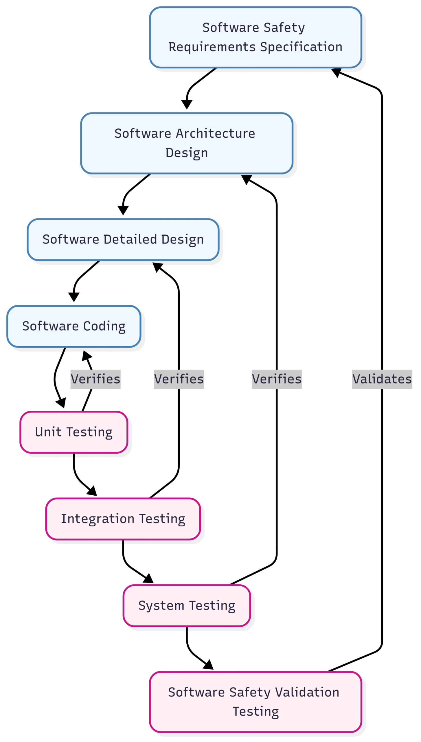
Similar to hardware, software development must follow a stringent lifecycle. The most common representation of this lifecycle in the context of IEC 61508 is the V-model. The V-model emphasizes the relationship between the development phases and the corresponding testing phases.
Block Diagram Description: The Software Safety V-Model (IEC 61508-3)
Avoiding and Controlling Systematic Failures
The core of IEC 61508-3 is a comprehensive set of measures and techniques aimed at avoiding the introduction of faults during the software development process and controlling any residual faults that may remain. The rigor of these measures is directly proportional to the target SIL.
For higher SILs, the standard mandates more stringent techniques, such as:
Formal methods: Using mathematical techniques to specify, develop, and verify the software.
Use of restricted language subsets: Employing coding standards like MISRA C to avoid potentially dangerous language features.
Diverse programming: Having two independent teams develop the same software to reduce the chance of common design flaws.
Static analysis: Using tools to analyze the source code for potential errors without executing it.
Dynamic analysis and testing: Rigorous testing of the software’s behavior under various conditions, including fault injection testing.
Software Verification and Validation
Verification and validation are two distinct but related processes that are critical throughout the software lifecycle:
Verification: This asks the question, “Are we building the product right?”. It involves checking that the output of each development phase meets the requirements of the previous phase. For example, verifying that the detailed design correctly implements the architectural design.
Validation: This asks the question, “Are we building the right product?”. It involves testing the final software to ensure that it meets the overall software safety requirements.
IEC 61508-3 provides extensive tables of recommended techniques for software verification and validation, with the level of recommendation (e.g., “Highly Recommended,” “Recommended”) depending on the SIL.
Systematic Capability: The Common Thread
A concept that ties both hardware and software together is Systematic Capability (SC). SC is a measure of the confidence that the systematic safety integrity of a component meets the requirements of the specified SIL. It essentially reflects the rigor of the design, development, and manufacturing processes used to create the component.
A component will have an SC rating (e.g., SC 2, SC 3), which indicates the maximum SIL it can be used in from a systematic failure perspective. Even if a hardware component has excellent random failure characteristics (high SFF and HFT), its use in a higher SIL application may be limited by its SC. This is determined through a rigorous audit of the manufacturer’s quality and safety management systems.
For a complete safety function to achieve a certain SIL, all its components (hardware and software) must have an SC rating equal to or greater than the target SIL. This ensures that the entire system has been developed with the necessary level of discipline and control to prevent systematic failures.
Conclusion: A Holistic Approach to Safety
IEC 61508 Parts 2 and 3 provide a robust and detailed framework for ensuring the functional safety of hardware and software in safety-critical systems. The key takeaway is that achieving functional safety is not a one-time activity but a continuous process that requires a holistic and systematic approach.
For hardware, the focus is on building in resilience through fault tolerance and diagnostics to manage random failures. For software, the emphasis is on a highly disciplined development process to prevent and control systematic failures. The concept of Systematic Capability further underscores the importance of a strong safety culture and rigorous processes throughout the entire supply chain.
By understanding and applying the principles outlined in IEC 61508-2 and -3, engineers and organizations can design and build systems that not only meet regulatory requirements but, more importantly, provide the high level of safety and reliability that modern industrial applications demand. This deep dive has hopefully illuminated the path to navigating these critical parts of the standard, empowering you to build a safer future.