A Distributed Control System (DCS) rack is the central nervous system of any modern industrial plant. It houses the essential hardware modules that execute the complex logic, communication, and signal processing required for precise process control. Understanding the components inside this rack is crucial for engineers, technicians, and anyone involved in industrial automation.
This comprehensive guide delves deep inside a typical DCS rack, exploring the function, importance, and interplay of each module. We’ll use clear explanations and Mermaid diagrams to visualize how these components work together to ensure safe, efficient, and reliable plant operation.
What is a DCS Rack? The Backbone of Industrial Automation
A DCS is a control system for a manufacturing process or plant in which control elements are distributed throughout the system. A DCS rack, also known as a chassis or cabinet, is the physical enclosure that houses the core electronic components of this system. It’s more than just a metal box; it’s a highly organized, engineered environment designed for reliability, scalability, and maintainability.
Think of it as the main server rack in an IT data center, but purpose-built for the harsh and demanding conditions of an industrial environment. Inside this rack, various electronic modules work in concert to interpret signals from the field (like temperature, pressure, and flow sensors), execute control strategies, and send commands back to final control elements (like valves, motors, and pumps).
The primary purpose of the DCS rack is to:
Provide Power: Distribute stable and often redundant power to all modules.
House Controllers: Securely mount the central processing units (CPUs) or controllers that run the control logic.
Interface with the Field: Connect to thousands of input and output (I/O) signals from plant-floor devices.
Facilitate Communication: Enable communication between controllers, I/O modules, and higher-level systems like operator workstations and historians.
Ensure Reliability: Support redundant configurations to eliminate single points of failure and ensure continuous operation.
Let’s open the door and examine the different modules you’ll find inside.
1. The Power Supply Unit (PSU): The Heartbeat of the System
Every electronic device needs power, and the modules in a DCS rack are no exception. The Power Supply Unit (PSU) is arguably the most critical component because, without it, nothing else functions. Its job is to take the main plant power (e.g., 120/240 VAC or 125 VDC) and convert it into the stable, low-voltage DC power (typically 24 VDC) that the electronic modules require.
Industrial environments are notorious for electrical noise, voltage sags, and power surges. Therefore, a DCS PSU is not just a simple power converter. It’s an industrial-grade unit designed for high reliability and clean power delivery.
Key Features:
Redundancy: This is the most important feature. Most critical DCS racks use a 1+1 redundant power supply configuration. Two PSUs are installed, and both are active or one is on standby. If one unit fails, the other seamlessly takes over the full load without any interruption to the process. This is crucial for preventing costly plant shutdowns.
Load Sharing: In many redundant setups, both PSUs actively share the load. This reduces the stress on each unit, extending its lifespan.
Diagnostics and Alarms: PSUs have built-in monitoring. They can report their health status (e.g., output voltage, load current, internal temperature) back to the DCS controller. If a fault is detected, an alarm is immediately sent to the operators.
Overload and Short-Circuit Protection: Protects the PSU and all connected modules from damage in case of an electrical fault.
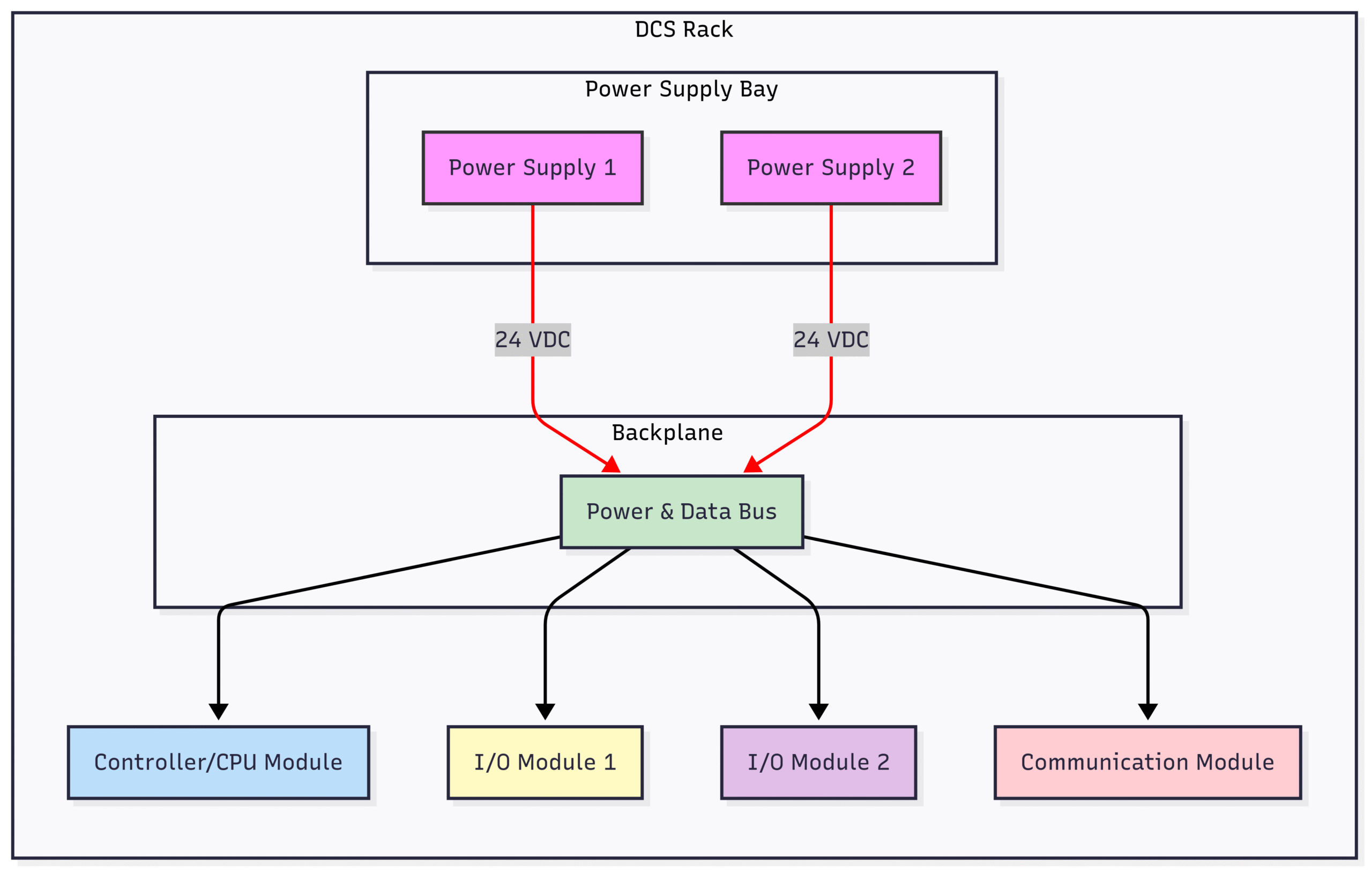
As the diagram shows, the redundant PSUs provide a reliable power source to the rack’s backplane, which is a circuit board with connectors that distributes power and data signals to all the modules plugged into it.
2. The Controller/CPU Module: The Brain of the Operation
The Controller or Central Processing Unit (CPU) module is the brain of the DCS. This powerful microprocessor is where the control logic is stored and executed. It continuously solves the complex algorithms, mathematical equations, and sequential logic (like PID loops, interlocking, and startup sequences) that define the control strategy for a specific plant area.
The controller’s primary responsibilities include:
Reading process variable (PV) data from the input modules.
Executing the configured control logic based on this data.
Writing output values to the output modules to manipulate final control elements.
Communicating with other controllers and supervisory systems.
Managing system diagnostics and alarms.
Modern controllers are incredibly powerful, capable of executing thousands of control loops in fractions of a second. The speed and determinism of the controller are critical for controlling fast-moving processes and ensuring process stability.
Redundancy in Controllers: Just like power supplies, controllers in critical applications are almost always redundant. A primary controller executes the logic, while a secondary, backup controller runs in parallel, continuously monitoring the primary’s health. In the event of a fault in the primary controller, a bumpless transfer occurs. The backup controller takes command instantly, using the last known good data to continue controlling the process without any disruption or “bump” to the operation.

This diagram illustrates the primary/backup relationship. The primary controller actively communicates with the I/O bus and the control network, while the backup controller stays synchronized and ready to take over at a moment’s notice.
3. Input/Output (I/O) Modules: The Senses and Hands
If the controller is the brain, the Input/Output (I/O) modules are the senses and hands of the DCS. They provide the physical connection between the digital world of the controller and the analog and discrete world of the plant floor. Their job is to condition and convert signals from thousands of field devices into a digital format the controller can understand, and vice-versa.
I/O modules are the most numerous components in a DCS rack. They come in four main flavors:
Analog Input (AI) Modules
These modules “sense” the real world. They connect to instruments that measure continuous variables.
Function: Converts continuous analog signals from field sensors into digital values.
Examples of Signals:
4-20 mA: The most common industrial standard for transmitters measuring pressure, temperature, level, and flow.
1-5 V: Another common voltage standard.
Thermocouples (T/C): Directly measures temperature. AI cards for T/Cs include special cold-junction compensation circuitry.
Resistance Temperature Detectors (RTD): Measures temperature based on resistance changes.
Key Feature: Isolation. Each channel on an AI card is often electrically isolated from others to prevent ground loops and signal interference, ensuring signal integrity.
Analog Output (AO) Modules
These modules “act” on the real world in a continuous manner.
Function: Converts digital values from the controller into analog signals to drive final control elements.
Examples of Devices Controlled:
Control Valves: The 4-20 mA signal positions the valve anywhere from 0% (fully closed) to 100% (fully open).
Variable Speed Drives (VSDs): A 4-20 mA or 0-10 V signal can control the speed of a motor.
Dampers and Louvers: Positioned using an analog signal.
Digital Input (DI) Modules
Also known as Discrete Input modules, these components sense on/off states.
Function: Reads the status of two-state devices.
Examples of Signals:
Motor Status: Is the motor running or stopped?
Limit Switches: Is a valve fully open or fully closed?
Push Buttons: Has the operator pressed the start button?
Pressure/Level Switches: Has the pressure exceeded a high limit?
Signal Type: Typically reads a voltage (e.g., 24 VDC for “on” and 0 VDC for “off”).
Digital Output (DO) Modules
Also known as Discrete Output modules, these components command devices to turn on or off.
Function: Sends on/off commands from the controller to field devices.
Examples of Devices Controlled:
Motors: Start/stop commands for fixed-speed motors via a motor control center (MCC).
Solenoid Valves: Open or close a block valve.
Alarms and Lights: Activate a warning beacon or an alarm horn.

This diagram visualizes the complete signal flow: from field sensors through input modules to the controller, and from the controller through output modules to the final control elements.4. Communication Modules: The System’s Network Interface
Modern automation is all about connectivity. The Communication Module acts as a gateway, allowing the DCS controller to talk to other systems and devices over various industrial networks. A rack might contain several different communication modules, each dedicated to a specific protocol.
Functions of a Communication Module:
Supervisory Network: Connects the controller to the Human-Machine Interface (HMI) operator workstations, engineering stations, and data historians on the plant’s process control network (PCN). This typically uses standard Ethernet.
Peer-to-Peer: Allows multiple controllers in different racks to share data and coordinate control strategies without having to go through a supervisory server. This is essential for integrated control of large plant units.
Fieldbus Integration: Interfaces with intelligent field devices using digital communication protocols like FOUNDATION Fieldbus, PROFIBUS, or HART. This allows for richer data (diagnostics, device status) to be collected from smart instruments beyond just the primary process variable.
Third-Party Integration: Connects to other control systems like Programmable Logic Controllers (PLCs), safety systems, or specialized package units (e.g., a large compressor with its own controller) using protocols like Modbus or OPC UA.
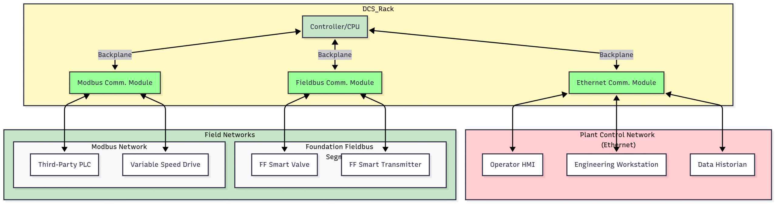
This diagram illustrates how communication modules act as bridges, connecting the central controller to a wide variety of other systems both at the supervisory level and in the field.5. Termination Assemblies and Rack Layout: The Physical Connection
While the modules get all the glory, how they connect to the hundreds or thousands of field wires is a critical aspect of rack design. Field wiring is not typically connected directly to the I/O module cards themselves. Instead, it lands on Termination Assemblies.
A Termination Assembly is essentially a sophisticated set of terminal blocks, often mounted in the same cabinet or a marshalling cabinet. It provides a clean and organized interface point. A pre-fabricated multi-core cable then connects the termination assembly to the front of the corresponding I/O module.
Advantages of using Termination Assemblies:
Organization: Keeps high-voltage field wiring separate from the sensitive low-voltage electronics.
Maintainability: A technician can disconnect the main cable from the I/O module and replace the module without having to unwire dozens of individual field cables. This is known as hot-swapping (if the system supports it).
Signal Conditioning: Termination assemblies can include space for fuses, relays, or intrinsic safety barriers right at the termination point.
Testing: Provides easy-to-access test points for troubleshooting field wiring without disconnecting it.
Rack Layout and Physical Considerations
The physical layout of the rack is engineered for reliability.
Cooling: Modules generate heat. Racks are equipped with cooling fans, typically at the bottom and top, to create airflow and prevent overheating, which can lead to premature component failure.
Grounding: Proper grounding is paramount in an industrial setting to protect against electrical noise and ensure personnel safety. A dedicated grounding bar is a standard feature in every DCS cabinet.
Wiring Channels: Wires are neatly routed through dedicated channels or ducts to prevent a “rat’s nest” of cables, which is a maintenance and safety nightmare.
6. Safety and Redundancy: Ensuring Failsafe Operation
In many industries like oil and gas, chemical production, and power generation, failure is not an option. A DCS must operate reliably and, more importantly, fail predictably and safely. This is where the concepts of redundancy and Safety Instrumented Systems (SIS) come into play.
We’ve already discussed redundancy for power supplies and controllers. I/O modules can also be made redundant. For a critical measurement, two separate AI modules might read the same transmitter, or the system might use two transmitters. The controller then uses voting logic (e.g., taking the average or selecting the healthier signal) to ensure a single sensor or card failure doesn’t trip the plant.
Safety Instrumented Systems (SIS)
For the most critical safety functions (e.g., an emergency shutdown system), a separate, independent protection layer is used. This is the Safety Instrumented System (SIS) or Safety Shutdown System (ESD). An SIS often uses its own dedicated racks, controllers, and I/O modules that look very similar to the main DCS (sometimes from the same vendor).
However, SIS components are certified to a specific Safety Integrity Level (SIL), typically SIL 2 or SIL 3, according to the IEC 61508/61511 standards. This certification guarantees a very high level of reliability and a very low probability of failure on demand. The SIS controller runs much simpler logic focused purely on bringing the process to a safe state when a dangerous condition is detected, regardless of what the main DCS is doing.
Conclusion: The Unsung Hero of Modern Industry
The DCS rack is a marvel of industrial engineering—a dense, powerful, and incredibly reliable hub of automation technology. From the redundant power supplies that provide its lifeblood to the intelligent controllers that act as its brain, and from the versatile I/O modules that serve as its senses to the communication modules that give it a voice, every component has a critical role.
By working together in a carefully orchestrated system, these modules provide the robust, non-stop control that allows industries to produce the goods and energy we rely on every day, all while maintaining the highest levels of safety and efficiency. The next time you see a row of unassuming grey cabinets in a plant control room, you’ll know that inside lies the very heart of the operation.
Frequently Asked Questions (FAQ)
Q1: What’s the difference between a DCS and a PLC? A1: While both control industrial processes, a PLC (Programmable Logic Controller) is typically used for smaller, faster, and more discrete control tasks (e.g., controlling a single machine). A DCS (Distributed Control System) is designed for large-scale, continuous process control across an entire plant. DCSs have integrated tools for HMI, alarming, and data historization, and are built with redundancy at their core.
Q2: What does “hot-swappable” mean for a DCS module? A2: Hot-swappable means a module can be removed and replaced while the rest of the system is still powered on and operating, without interrupting the process. This is a critical feature for maintenance in plants that run 24/7. Redundant modules are inherently designed to be hot-swapped.
Q3: What is a “backplane” in a DCS rack? A3: The backplane is a printed circuit board at the rear of the rack chassis where all the modules plug in. It contains parallel data buses and power buses that connect all the modules, allowing them to communicate with each other and the controller at high speeds.
Q4: What is HART protocol? A4: HART (Highway Addressable Remote Transducer) is a hybrid communication protocol that superimposes a low-level digital signal on top of the standard 4-20 mA analog signal. It allows technicians to get additional diagnostic information from a smart instrument or configure it remotely without interfering with the primary process control signal. Many modern AI and AO cards support HART communication.
Q5: How long do DCS systems typically last? A5: DCS systems are built for longevity. The hardware in a DCS rack can have a lifespan of 15-20 years or more. Over time, vendors release new generations of controllers and I/O modules, and plants typically go through phased migration projects to upgrade their aging systems to newer technology.