The international standard IEC 61131-3 defines the five most common PLC programming languages, which are split into two categories: graphical and textual.
Graphical Languages:
Ladder Logic (LD): The most popular language, it visually mimics electrical relay logic circuits, making it intuitive for electricians and technicians. It’s excellent for discrete control and straightforward sequential operations.
Function Block Diagram (FBD): This language represents functions as blocks connected by wires. It’s useful for visualizing signal and data flows, especially in systems with continuous process control.
Sequential Function Chart (SFC): Designed for managing complex, step-by-step processes. It uses a flowchart-like structure of steps and transitions to organize the program, making it easy to troubleshoot sequential operations.
Textual Languages:
Structured Text (ST): A high-level, structured language similar to Pascal or C. It is ideal for complex mathematical calculations, algorithms, and data manipulation that would be cumbersome in graphical languages.
Instruction List (IL): A low-level, text-based language that resembles assembly. While very efficient and fast, its complexity has led to a decline in its use in favor of more modern and user-friendly languages.
Choosing the right language depends on the application’s complexity, the programmer’s background, and the specific control task at hand.
Introduction to PLC Programming Languages: Ladder Logic and Beyond
Welcome to the world of industrial automation! At the heart of nearly every modern factory, manufacturing plant, or automated process lies a powerful little computer known as the Programmable Logic Controller (PLC). This ruggedized device is the brain of the operation, executing commands, monitoring processes, and ensuring everything runs smoothly, safely, and efficiently. But how do we tell the PLC what to do? The answer lies in PLC programming languages.
For aspiring automation engineers, technicians, or anyone curious about the technology that builds our world, understanding these languages is the first step toward mastery. While it might sound daunting, the field is more accessible than you think, thanks to a standardized set of languages designed for clarity and function. This comprehensive guide will introduce you to the core languages defined by the IEC 61131-3 standard, starting with the foundational Ladder Logic and venturing into the powerful graphical and textual alternatives. Let’s dive in and decode the language of automation. 🤖
What is a PLC and Why is it Essential?
Before we jump into the programming languages, let’s briefly touch upon the PLC itself. A Programmable Logic Controller is an industrial-grade computer designed to withstand harsh environments—think extreme temperatures, vibrations, humidity, and electrical noise. Unlike your desktop PC, a PLC is built for reliability and real-time control.
Its primary job is to automate electromechanical processes. This could be anything from a simple task, like turning a motor on and off, to controlling an entire assembly line or managing a complex chemical process. The PLC achieves this by:
Reading Inputs: It continuously monitors the state of input devices like sensors, buttons, and switches.
Executing a Program: It processes this input information by executing a user-written program.
Controlling Outputs: Based on the program’s logic, it energizes or de-energizes output devices like motors, solenoids, lights, and valves.
This scan cycle—Read Inputs, Execute Program, Update Outputs—happens thousands of times per second, allowing for precise and responsive control. The magic that dictates the PLC’s behavior is the program, which is written in one of the specialized languages we’re about to explore. The IEC 61131-3 standard was established to bring a standardized approach to PLC programming, ensuring that skills are more transferable across different PLC brands like Siemens, Rockwell Automation (Allen-Bradley), Schneider Electric, and Omron.
The King of PLC Programming: Ladder Logic (LD)
If you learn only one PLC language, make it Ladder Logic (LD). It is, by far, the most widely used and recognized PLC programming language in the world, especially in North America. Its popularity stems from its brilliant design, which mimics the appearance of electrical relay schematics.
From Relays to Rungs
In the days before PLCs, industrial control was accomplished using vast cabinets of physical relays, timers, and counters, all wired together. When PLCs were introduced in the late 1960s, they needed a programming language that electricians and technicians, the primary users of the technology, could easily understand and adopt. Ladder Logic was the perfect solution. It replaced the physical wiring of relays with a graphical, software-based representation.
A Ladder Logic program is structured like a ladder:
Rails: Two vertical lines, called rails, represent the power supply (a positive rail on the left and a negative or neutral rail on the right).
Rungs: Horizontal lines, called rungs, connect the rails. The logic is placed on these rungs.
Logic Execution: The PLC “scans” the ladder from top to bottom and from left to right on each rung. For a rung to be “true,” there must be a continuous logical path from the left rail to the right.
Core Components of Ladder Logic
The basic building blocks of Ladder Logic are contacts (inputs) and coils (outputs).
Contacts (Inputs): These represent conditions that must be met. They are analogous to switches or relay contacts.
Normally Open (NO) Contact
—[ ]—: This contact is “false” by default. It becomes “true” when the corresponding input bit is on (e.g., a button is pressed).Normally Closed (NC) Contact
—[\]—: This contact is “true” by default. It becomes “false” when the corresponding input bit is on (e.g., an emergency stop button is pressed, breaking the circuit).
Coils (Outputs): These represent the actions to be taken. They are analogous to relay coils, motors, or indicator lights.
Output Coil
—( )—: If the logic on the rung preceding the coil is “true,” the coil is energized, turning on the corresponding output device.
Example: A Simple Motor Start/Stop Circuit
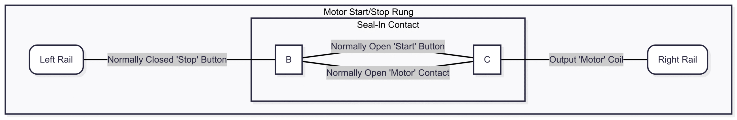
Let’s look at one of the most classic examples: a three-wire motor start/stop control circuit. This circuit uses a momentary “Start” button, a momentary “Stop” button, and a motor output. A key feature is the “seal-in” or “latching” contact, which keeps the motor running after the “Start” button is released.
Here’s the logic:
Pressing the “Start” button will turn the motor on.
The motor should remain on even after the “Start” button is released.
Pressing the “Stop” button will turn the motor off.
How it works:
Starting: When the “Start” button is pressed, the NO ‘Start’ contact becomes true. Since the ‘Stop’ button is NC and hasn’t been pressed, it is also true. This creates a true logical path to the ‘Motor’ coil, turning it on.
Sealing-In: As soon as the ‘Motor’ coil is energized, the NO ‘Motor’ contact (wired in parallel with the ‘Start’ button) also becomes true. Now, even if the user releases the ‘Start’ button, the logic remains true through this seal-in contact.
Stopping: When the “Stop” button is pressed, the NC ‘Stop’ contact becomes false, breaking the logical continuity of the rung and de-energizing the ‘Motor’ coil. The seal-in contact also becomes false, and the circuit resets to its initial state.
Pros of Ladder Logic:
✅ Intuitive: Easy for people with an electrical background to learn and troubleshoot.
✅ Visual: Excellent for debugging because the flow of logic is visually represented.
✅ Standardized: The core concepts are the same across all PLC brands.
Cons of Ladder Logic:
❌ Limited for Complex Math: Performing complex mathematical calculations or data array manipulation can be very cumbersome.
❌ Poor for Sequential Control: While possible, managing complex sequences with many steps can lead to messy, hard-to-read “spaghetti code.”
Going Graphical: Function Block Diagram (FBD)
The second graphical language in the IEC 61131-3 standard is the Function Block Diagram (FBD). Where Ladder Logic excels at discrete bit logic, FBD shines in applications involving continuous signal flow and data processing. It’s particularly popular in the process control industries (e.g., chemical, oil and gas).
An FBD program looks like a circuit diagram. It consists of blocks, which are pre-programmed or custom-made functions, connected by lines or “wires.” Data flows from the outputs of one block to the inputs of another.
The Anatomy of a Function Block
Each block represents a specific function, such as:
Logical Operations: AND, OR, XOR, NOT
Timers: On-Delay (TON), Off-Delay (TOF)
Counters: Count Up (CTU), Count Down (CTD)
Mathematical Operations: ADD, SUB, MUL, DIV
Process Control: PID loops (Proportional-Integral-Derivative)
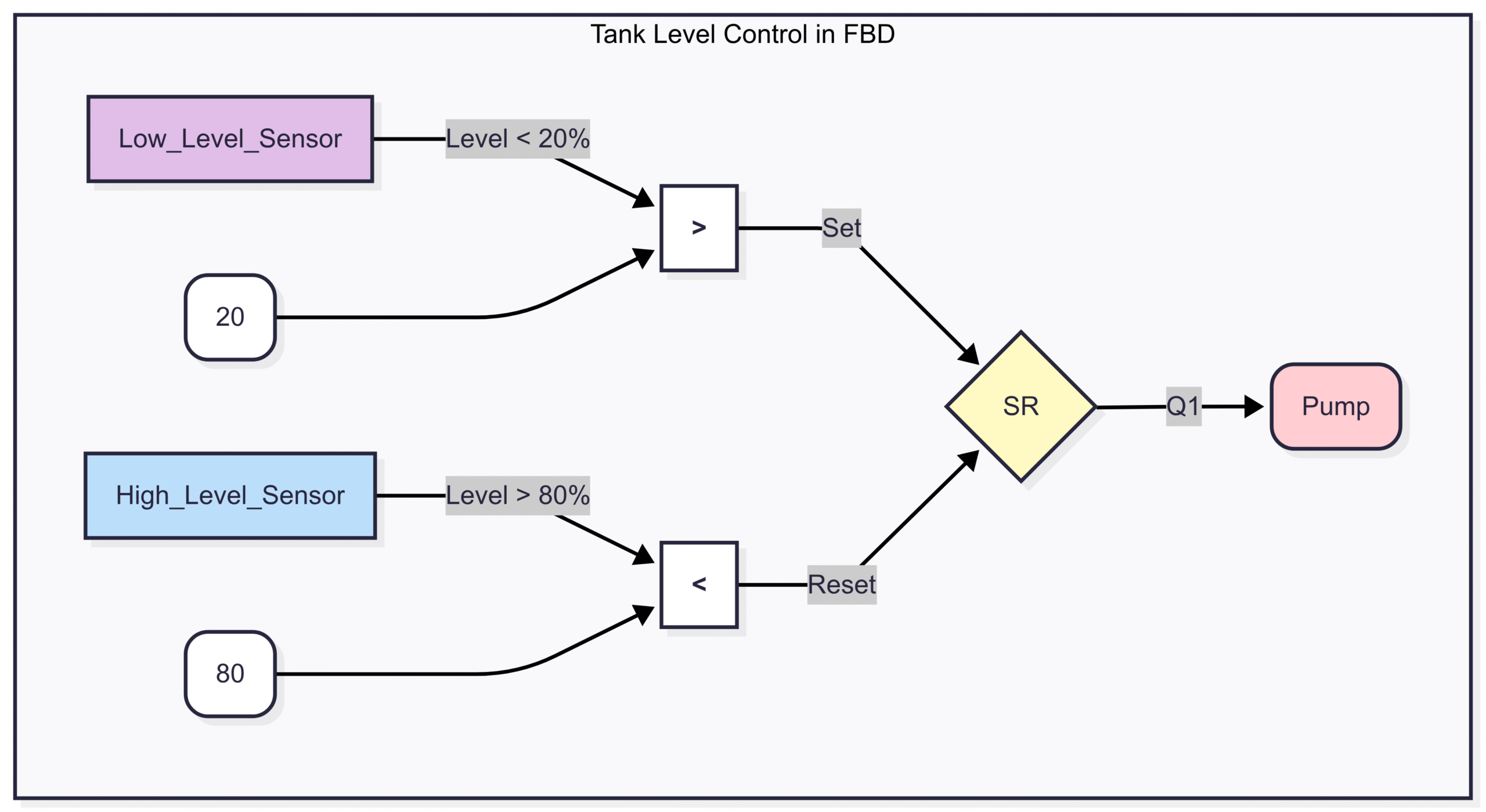
Example: A Simple Tank Level Control
Imagine we want to turn on a pump to fill a tank when the level is low and turn it off when it’s high. We can use an FBD to represent this logic clearly.
How it works:
We use two comparison blocks (
>and<). One checks if the tank level is greater than 20% (acting as a low-level trigger), and the other checks if the level is less than 80% (high-level trigger).The outputs of these comparison blocks feed into an SR Flip-Flop (Set/Reset).
When the level drops below 20%, the
>block is false, which we can invert to Set the flip-flop, turning the pump on.When the level rises above 80%, the
<block becomes false, which can Reset the flip-flop, turning the pump off.The output
Q1of the flip-flop directly controls the pump.
Pros of Function Block Diagram:
✅ Visual Flow: Clearly shows the flow of data and the relationship between different functions.
✅ Great for Process Control: Ideal for analog signals and complex control loops like PID.
✅ Reusable Code: Function blocks can be encapsulated and reused throughout a project or in future projects.
Cons of Function Block Diagram:
❌ Large Sheets: Complex programs can take up a lot of space on the screen, requiring extensive scrolling.
❌ Can be Overwhelming: For simple discrete logic, FBD can be more complex than necessary compared to Ladder Logic.
For the Programmers: Structured Text (ST)
For those coming from a computer science or software development background, Structured Text (ST) will feel immediately familiar. It is a high-level, text-based language with a syntax similar to Pascal, C, or modern languages like Python.
ST is the go-to language for tasks that are difficult or impossible to implement cleanly in graphical languages. This includes:
Complex mathematical algorithms (e.g., trigonometry, statistics).
Working with arrays and data structures (recipes, sorting).
Looping and conditional execution (FOR loops, WHILE loops).
String manipulation.
The Power of Text
An ST program uses statements, variables, and conditional logic. You can use IF...THEN...ELSE statements, CASE statements for multiple conditions, and FOR or WHILE loops for repetitive tasks.
Example: Motor Start/Stop in Structured Text
Let’s revisit our simple motor start/stop circuit, but this time written in ST.
(* Motor Start/Stop Logic in Structured Text *)

// The IF statement checks the conditions on every scan
IF Stop_Button THEN
    Motor_Output := FALSE; // Stop button is pressed, turn motor OFF
ELSIF Start_Button THEN
    Motor_Output := TRUE;  // Start button is pressed, turn motor ON
END_IF;

// The logic above is incomplete because it's not a latch.
// A proper latching circuit in ST would be:

Motor_Output := (Motor_Output OR Start_Button) AND NOT Stop_Button;
The second, single-line version is a more concise and accurate representation of the latching logic. It states that the Motor_Output should be TRUE if (Motor_Output is already TRUE OR the Start_Button is pressed) AND the Stop_Button is NOT pressed. This perfectly mirrors the logic of our original Ladder Logic rung.
Pros of Structured Text:
✅ Powerful: Best language for complex math, data handling, and algorithms.
✅ Concise: Complex logic can be expressed in a few lines of code.
✅ Portable: Logic written in ST is often easier to port to other platforms or languages.
Cons of Structured Text:
❌ Less Visual: It can be harder to visualize the program flow and troubleshoot in real-time compared to LD or FBD.
❌ Steeper Learning Curve: For those without a traditional programming background, ST can be more challenging to learn.
Organizing the Chaos: Sequential Function Chart (SFC)
What if your process isn’t continuous but happens in a distinct, ordered sequence? For example, a bottling line:
Wait for a bottle.
Fill the bottle.
Cap the bottle.
Apply a label.
Move the bottle down the conveyor.
Trying to program this with Ladder Logic can result in a complex web of interlocking latches and timers that is a nightmare to debug. This is where Sequential Function Chart (SFC) comes in.
SFC is a graphical language that organizes the program into a flowchart. It doesn’t replace the other languages; it acts as a manager or an orchestrator. The actual logic within each step is typically written in another language, like Ladder Logic or Structured Text.
The Building Blocks of SFC
An SFC program is built from three main components:
Steps: These represent a state in the process. A step is either active or inactive. The actions associated with a step are only executed when the step is active.
Transitions: These are the conditions that allow the program to move from one step to the next. A transition is linked to a condition written in LD, ST, or another language. When the condition becomes true, the PLC deactivates the current step and activates the next one.
Actions: These are the actual instructions (e.g., “turn on motor,” “open valve”) that are executed within a step.
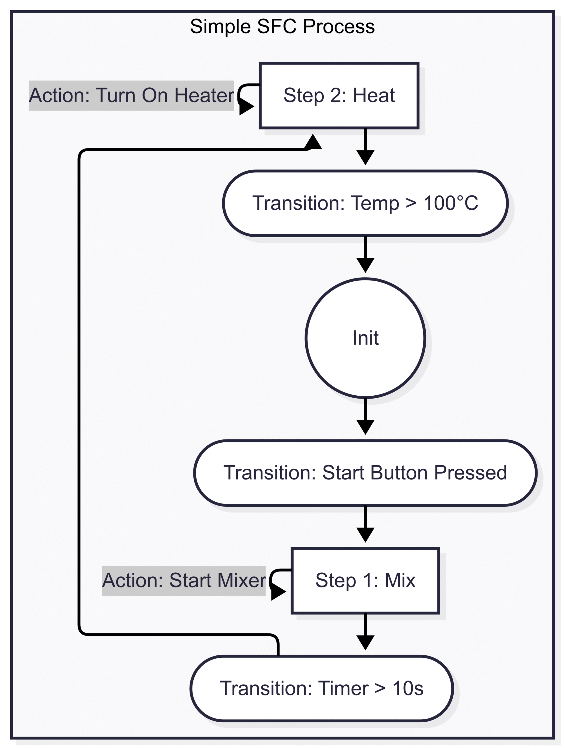
Example: A Simple Two-Step Sequence
Let’s visualize a simple process: Mix ingredients for 10 seconds, then heat the mixture until it reaches 100°C.
How it works:
The program starts at the
Initial_Step.When the
Start Button is Pressed(Transition T1), the PLC deactivates the initial step and activatesStep 1: Mix.While
Step 1is active, theMixeris turned on. A timer also starts.Once the
Timer > 10s(Transition T2), the PLC deactivatesStep 1and activatesStep 2: Heat. The mixer turns off, and the heater turns on.When the
Temp > 100°C(Transition T3), the PLC deactivatesStep 2and cycles back to theInitial_Step, waiting for the next start command.
Pros of Sequential Function Chart:
✅ Superior Organization: Perfect for managing complex, sequential operations.
✅ Easy Troubleshooting: You can instantly see which step of the process is currently active, dramatically speeding up diagnostics.
✅ Modularity: Encourages breaking down a large process into smaller, manageable steps.
Cons of Sequential Function Chart:
❌ Not a Standalone Language: It acts as a structural overlay; you still need to program the actions and transitions in another language.
❌ Overkill for Simple Tasks: For a simple start/stop circuit, using SFC would be unnecessary.
The Old Timer: Instruction List (IL)
The final language defined by the standard is Instruction List (IL). It is a low-level, text-based language that strongly resembles assembly language. Each line of code corresponds to a very basic instruction, like “Load a value,” “AND it with another value,” or “Store the result.”
In the early days of PLCs, IL was valued for its speed and memory efficiency. Because it is so close to the machine code the PLC’s processor understands, it executes very quickly. However, with the massive increase in processor speed and memory in modern PLCs, this advantage is now negligible for most applications.
Example: Motor Start/Stop in Instruction List
// Motor Start/Stop Logic in Instruction List
LD     Start_Button
OR     Motor_Output
ANDN   Stop_Button
ST     Motor_Output
Explanation:
LD Start_Button: Load the value ofStart_Buttoninto the accumulator.OR Motor_Output: Perform a logical OR with the value ofMotor_Output.ANDN Stop_Button: Perform a logical AND with the NOT (inverted) value ofStop_Button.ST Motor_Output: Store the final result inMotor_Output.
While efficient, IL is difficult to read, debug, and maintain. Its use has significantly declined, and many modern PLC programming environments discourage its use in favor of more user-friendly languages like ST or FBD.
Choosing the Right Language for the Job
So, which language should you use? The best automation engineers don’t have a single favorite language; they have a toolbox. They choose the best tool for the specific task at hand.
For discrete on/off logic and simple machine control: Start with Ladder Logic. Its visual nature is perfect for troubleshooting.
For process control with analog signals and PID loops: Function Block Diagram is your best bet.
For complex math, data manipulation, or custom algorithms: Structured Text is the only practical choice.
For organizing a machine’s entire operational sequence: Use Sequential Function Chart to structure the program and then write the logic for each step in LD, FBD, or ST.
For highly optimized, time-critical code on older hardware: Instruction List might have been the answer, but today, this is a rare requirement.
Modern PLC development environments allow you to mix and match these languages within the same project. You can have a master SFC that calls program organization units (POUs) written in Ladder Logic for simple I/O, other POUs in Structured Text for calculations, and still others in FBD for process loops. This hybrid approach allows you to leverage the strengths of each language, resulting in a program that is efficient, readable, and easy to maintain.
The journey into PLC programming is a rewarding one that opens doors to a career in the dynamic field of industrial automation. By starting with the fundamentals of Ladder Logic and gradually expanding your knowledge to include FBD, ST, and SFC, you’ll be well-equipped to design and control the automated systems that shape our modern world.