Section 1: Foundations of Industrial Level Measurement
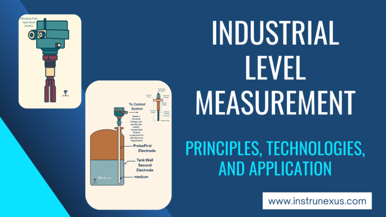
Level measurement is the determination of the position of a material’s surface within a vessel, such as a tank, silo, or container. This fundamental process variable is indispensable across a vast spectrum of industries, from water treatment and chemical processing to food and beverage production and power generation. The data derived from level instrumentation is not merely for volumetric accounting; it is a cornerstone of modern industrial automation, ensuring process efficiency, product quality, inventory management, and, most critically, operational safety.
1.1 The Critical Role of Level Measurement in Process Control and Safety
In any industrial process, the precise control of material levels is paramount. Accurate level data serves several critical functions:
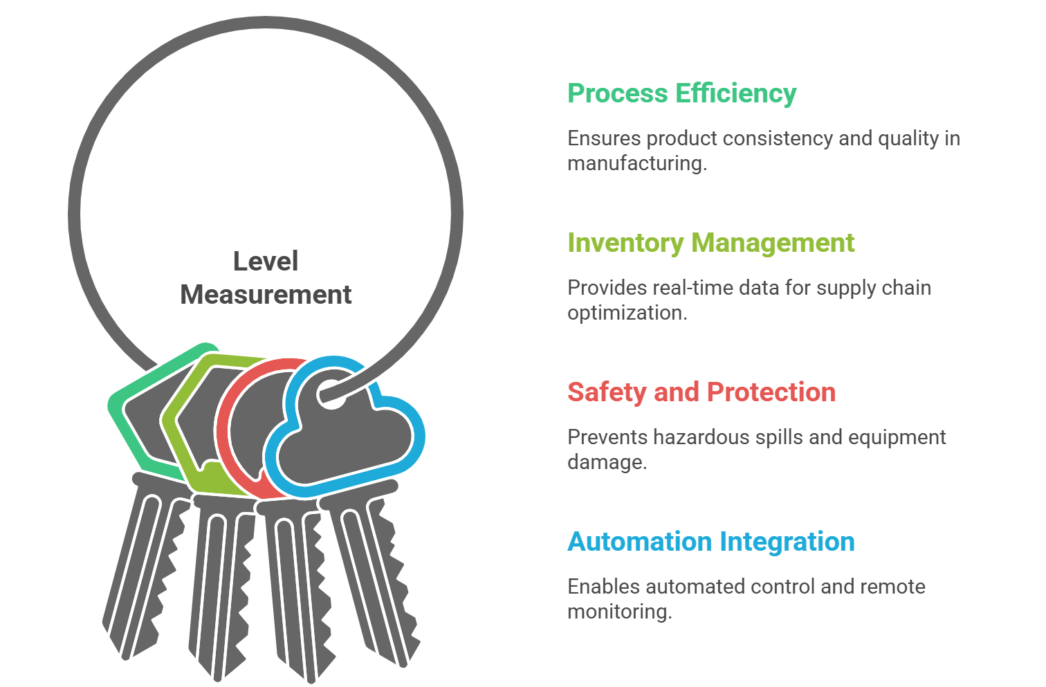
Process Efficiency and Quality Control: In manufacturing processes involving mixing, blending, or chemical reactions, exact level measurement is essential for controlling ingredient ratios and concentrations. This ensures product consistency and adherence to quality standards.
Inventory Management: Continuous monitoring of material levels in storage tanks and silos provides real-time inventory data. This information is vital for managing supply chains, preventing shortages that could lead to production downtime, and optimizing resource allocation.
Safety and Environmental Protection: The most critical function of level measurement is often safety. Level sensors are used to prevent vessel overfills, which can lead to hazardous material spills, equipment damage, environmental contamination, and significant financial loss. Conversely, they also provide “run-dry” protection for pumps and other equipment by ensuring a minimum level is maintained.
Automation and System Integration: Level transmitters provide the essential data that feeds into higher-level control systems, such as Programmable Logic Controllers (PLCs), Distributed Control Systems (DCS), and Supervisory Control and Data Acquisition (SCADA) systems. This integration enables automated control loops, remote monitoring, and data logging, which are foundational to modern, efficient plant operations. Improved measurement accuracy directly translates to reduced process variability, higher product quality, and less waste.
1.2 Differentiating Measurement Philosophies: Continuous vs. Point Level Detection
Level measurement instrumentation is broadly divided into two distinct philosophies based on the type of data required: continuous measurement and point level detection.
1.2.1 Continuous Level Measurement
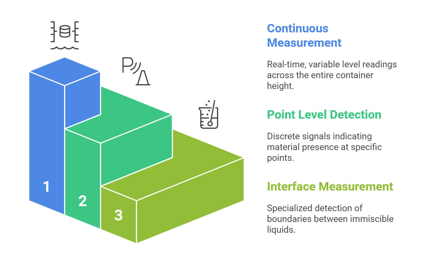
Continuous level measurement provides an uninterrupted, real-time reading of the material’s exact level over the entire height of the container. Instead of a simple binary state, it outputs a variable signal, often a 4-20mA analog signal or a digital value, that corresponds to the level, typically expressed as a height, percentage, or volume. This detailed, ongoing data is crucial for applications that require precise process control, inventory management, and trend analysis. Technologies primarily used for continuous measurement include Differential Pressure (DP), Radar, Ultrasonic, and Displacers.
1.2.2 Point Level Detection
Point level detection, also known as a level switch, indicates whether a material has reached a specific, predefined point in a vessel. It provides a discrete, “on/off” signal rather than a variable reading. These sensors are typically installed at critical high or low levels to trigger alarms, start or stop pumps, or actuate valves. Their primary function is to serve as a simple, reliable means of overfill prevention, dry-run protection, or basic process interlocking. Common point level technologies include vibrating fork switches, float switches, and rotating paddle switches.
1.2.3 Interface Measurement
A specialized subset of level measurement, interface measurement focuses on detecting the boundary between two immiscible liquids (e.g., oil and water) or between a liquid and a layer of foam or sediment. This capability is critical in separation processes, particularly in the oil and gas and chemical industries, to ensure product quality and process efficiency. Certain continuous technologies, such as Guided Wave Radar and Displacers, are exceptionally well-suited for this task.
1.3 The Primary Divide: Contact vs. Non-Contact Instrumentation
The initial and most fundamental decision in selecting a level measurement technology is whether the instrument will physically touch the process medium. This choice is not merely a technical preference but a strategic one, driven by a balance of initial cost, long-term maintenance, process contamination risks, and the physical and chemical properties of the material being measured. This decision immediately filters the available technology options, often before performance metrics like accuracy are even considered.
1.3.1 Contact Sensors
Contact level sensors are devices that must be in physical contact with the material they are measuring. This category includes a wide range of technologies such as displacers, capacitance probes, hydrostatic pressure sensors, and float switches.
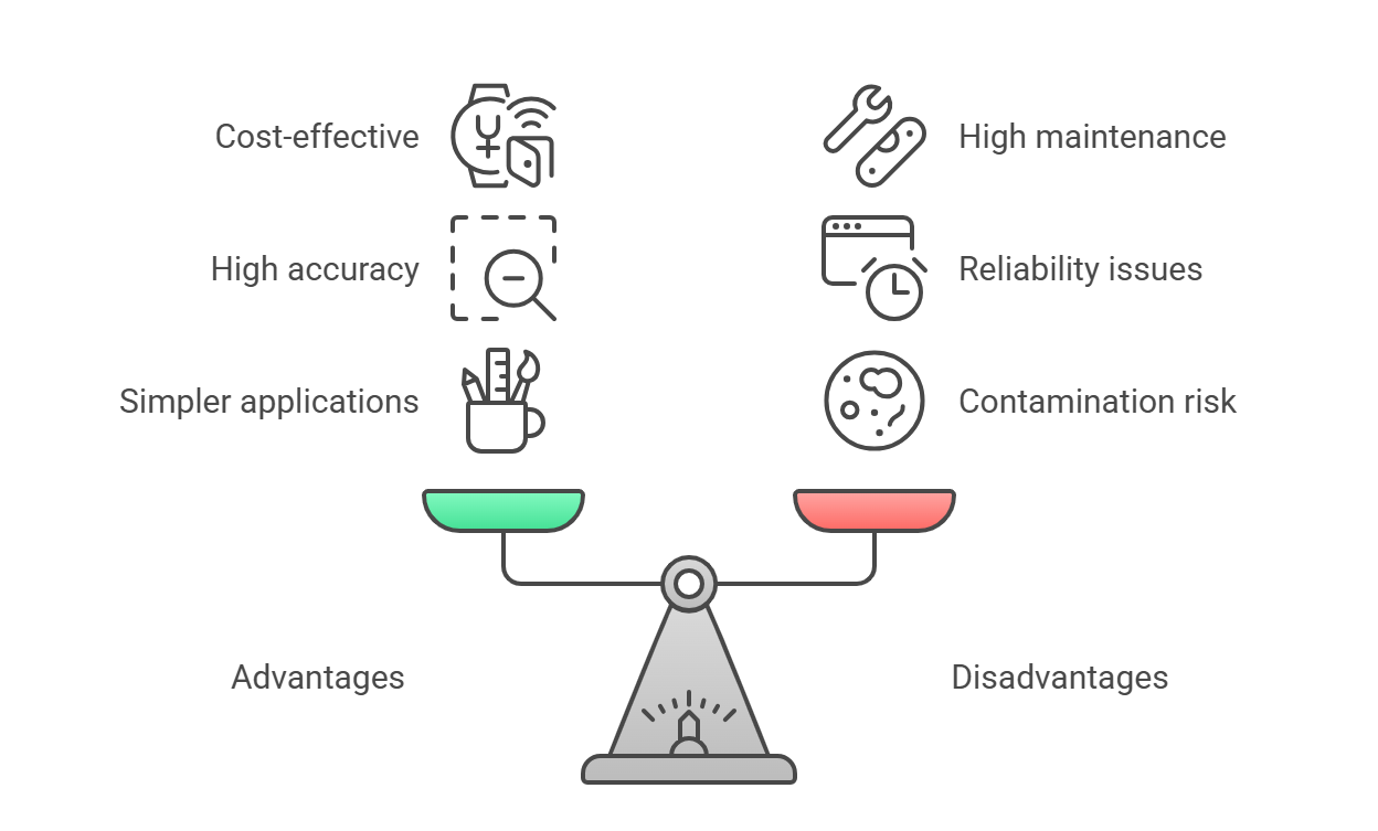
Advantages: They are often more cost-effective for simpler applications and can provide very high accuracy under stable, clean process conditions.
Disadvantages: Direct contact with the process medium makes them susceptible to wear, corrosion, abrasion, and material buildup (coating). This can lead to increased maintenance requirements, calibration drift, and eventual failure, particularly in aggressive, viscous, or abrasive media. In hygienic applications, such as food, beverage, and pharmaceuticals, contact sensors can introduce a risk of contamination if not designed with appropriate sanitary materials and connections.
1.3.2 Non-Contact Sensors
Non-contact sensors measure the level from a distance, typically mounted at the top of the vessel, without touching the process material. They rely on energy waves—such as microwaves (radar), sound waves (ultrasonic), or light waves (laser)—to determine the distance to the material’s surface.
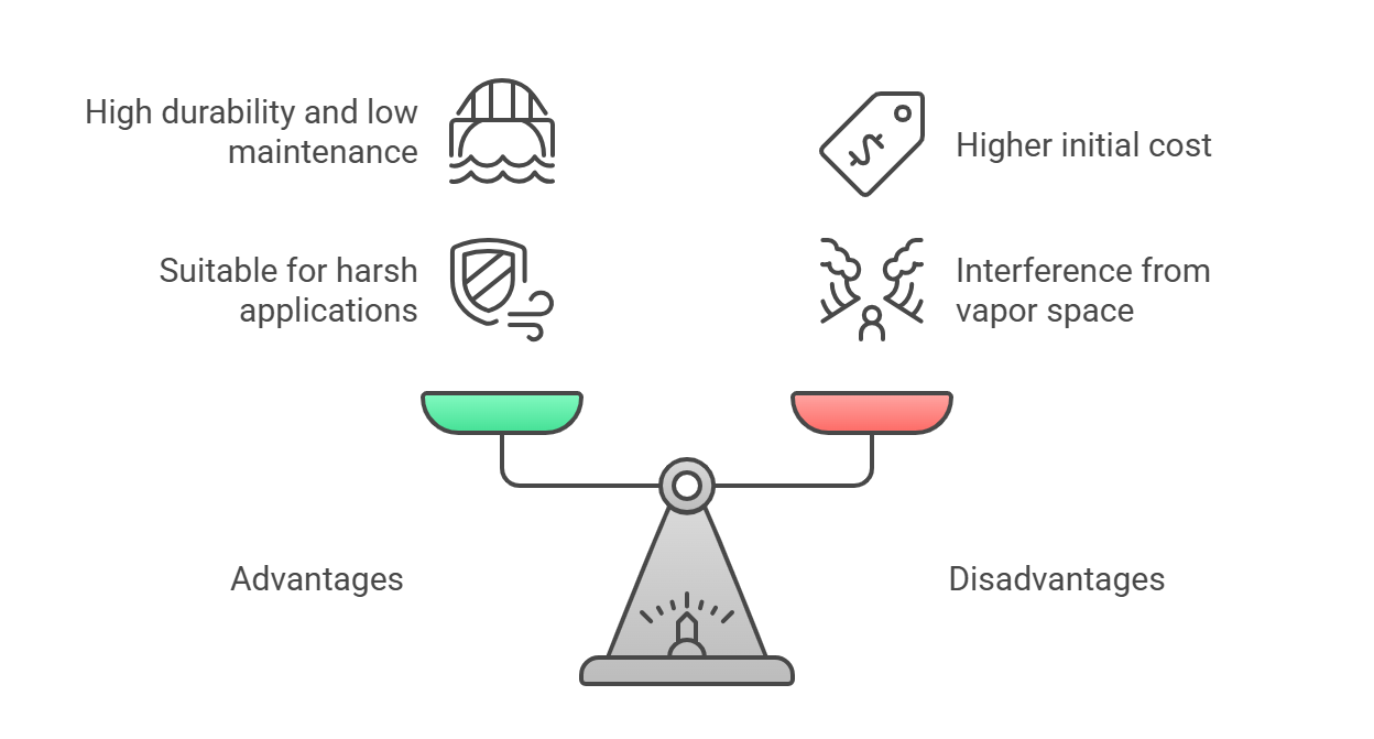
Advantages: The absence of physical contact makes these sensors exceptionally durable and low-maintenance, as they are immune to the corrosive, abrasive, or coating effects of the process medium. This makes them the preferred choice for harsh chemical applications, hygienic processes where contamination must be avoided, and for measuring viscous or sticky materials.
Disadvantages: Non-contact technologies generally have a higher initial purchase price compared to their contact counterparts. Their performance can also be affected by conditions in the vapor space above the material, such as heavy dust, foam, or vapor, which can interfere with the transmitted and reflected energy waves.
Section 2: In-Depth Analysis of Continuous Level Measurement Technologies
Continuous level transmitters form the backbone of modern process control and inventory management systems. The selection of an appropriate technology requires a deep understanding of its operating principle, inherent strengths, and critical limitations. This section provides a detailed engineering analysis of the most prevalent continuous measurement technologies.
2.1 Differential Pressure (DP) Transmitters: The Workhorse of Level Measurement
Differential pressure (DP) level measurement is one of the most established and widely used technologies in the process industries. It is an inferential method that does not measure level directly but calculates it based on the pressure exerted by a column of fluid.
2.1.1 The Hydrostatic Principle
The technology operates on the fundamental principle of hydrostatic pressure, which states that the pressure exerted by a fluid at rest is proportional to the height of the fluid column, its density (or specific gravity), and the gravitational constant (g). The formula is expressed as:
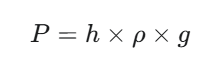
Where P is the hydrostatic pressure, h is the height of the fluid column, and ρ is the fluid density. By measuring the pressure (P) and knowing the fluid’s density (ρ), the transmitter’s electronics can accurately and reliably calculate the level (h).
2.1.2 Implementation in Open and Pressurized Vessels
The physical implementation of a DP system depends on whether the vessel is open to the atmosphere or is a closed, pressurized system.
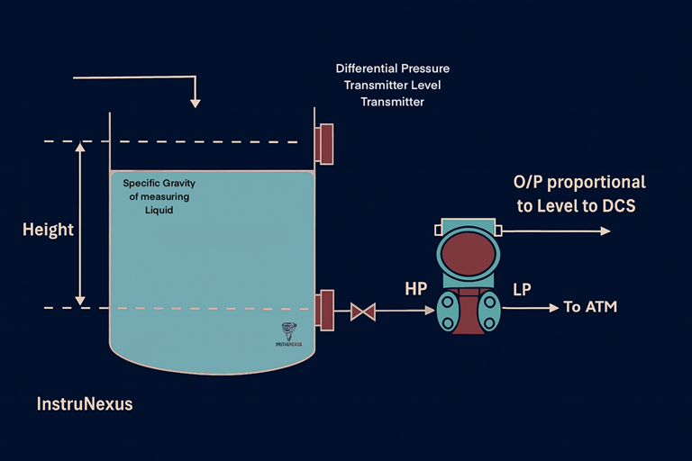
Open Vessels: In a tank vented to the atmosphere, a single pressure measurement is taken near the bottom of the vessel. This measurement represents the head pressure of the fluid column, which is then used to infer the level.
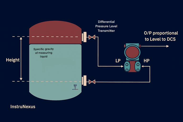
Pressurized (Closed) Vessels: In a sealed tank, the space above the liquid (the headspace or vapor space) is under pressure that is independent of the liquid level. To measure the liquid level accurately, this static pressure must be compensated for. This is achieved by measuring the pressure at two points. A high-side pressure port at the bottom of the tank measures the total pressure, which is the sum of the liquid head pressure (HP) and the static vapor pressure (LP). A low-side pressure port at the top of the tank measures only the static vapor pressure. The DP transmitter then subtracts the low-side pressure from the high-side pressure to isolate the liquid head pressure (P liquid=P total − P vapor), from which the level is calculated.
2.1.3 Signal Transmission: Impulse Lines vs. Electronic Remote Sensors (ERS)
The pressure measurements must be transmitted from the process taps to the DP sensor. Historically, this has been a significant source of maintenance and measurement error.
Traditional Methods: The connection to the vessel is traditionally made using either impulse lines or capillary lines. Impulse lines are hard pipes that allow the process fluid or gas to directly contact the transmitter’s diaphragm. While simple, they are highly susceptible to plugging in dirty or viscous services and can freeze in cold environments, requiring costly heat tracing.
Capillary systems use a sealed tube filled with a non-compressible fluid to transmit the pressure. However, long capillary tubes can introduce measurement delays (hysteresis), and temperature changes along the tube can cause the fill fluid to expand or contract, leading to significant measurement errors. A major drawback of both systems is that installation or maintenance typically requires the process to be shut down and the vessel drained.
Modern ERS Systems: The evolution to electronic differential pressure, or Electronic Remote Sensor (ERS) systems, has addressed many of these drawbacks. An ERS system uses two individual, discrete pressure sensors connected by a simple electrical cable. One sensor measures the high-side pressure, and the other measures the low-side pressure. The primary sensor’s electronics perform the subtraction to calculate the differential pressure and infer the level. This design eliminates the need for impulse or capillary lines, which in turn removes their associated maintenance issues and susceptibility to ambient temperature effects, leading to a more reliable and accurate measurement.
2.1.4 Performance Analysis, Advantages, and Limitations
Advantages: DP technology is proven, highly reliable, and versatile, capable of measuring the level of liquids and liquefied gases in both open and pressurized tanks. It is generally a cost-effective solution and is unaffected by the presence of internal tank structures like agitators or baffles.
Limitations: The single greatest limitation of DP level measurement is its critical dependence on a constant and known fluid density. As the calculation is based on the hydrostatic formula, any variation in the process fluid’s density or specific gravity will result in a direct and significant measurement error. This makes it unsuitable for applications where density changes due to temperature fluctuations, variations in product composition, or aeration. The technology also requires contact with the process medium, and the complex installation involving multiple vessel taps can be a drawback.
2.2 Radar Level Transmitters: Precision Through Electromagnetic Waves
Radar (Radio Detection and Ranging) level transmitters represent one of the most advanced and versatile technologies for continuous level measurement. They are non-contact instruments that offer high accuracy and reliability, especially in challenging process conditions.
2.2.1 The Time-of-Flight (ToF) Principle
The fundamental operating principle of a radar level transmitter is Time-of-Flight (ToF). The sensor, mounted at the top of a vessel, emits a high-frequency electromagnetic pulse (a microwave) directed towards the surface of the material being measured.
This pulse travels through the headspace, reflects off the material’s surface, and the echo returns to the sensor. An integrated timing circuit precisely measures the total transit time (t) of the pulse. Since the pulse travels at the speed of light (c), a known constant, the distance (D) from the sensor to the material surface can be calculated. Knowing the total height of the vessel, the transmitter can then determine the material level. This operating principle is a form of Time-Domain Reflectometry (TDR).
2.2.2 Transmission Methods: Pulse vs. Frequency Modulated Continuous Wave (FMCW)
Radar transmitters employ one of two primary transmission techniques:
Pulse Radar: This method involves transmitting short, discrete bursts of microwave energy and measuring the time until the echo returns. It is a straightforward implementation of the ToF principle.
Frequency Modulated Continuous Wave (FMCW): In this more advanced technique, the transmitter emits a continuous radar signal whose frequency is swept linearly over time. The reflected signal returns to the antenna with a time delay, and therefore its frequency is different from the frequency of the signal being transmitted at that instant. The difference between the transmitted and received frequencies is directly proportional to the distance to the surface. FMCW technology allows for a much stronger signal to be returned to the device, resulting in greater measurement accuracy and reliability, particularly in applications with agitated surfaces or weak reflections.
2.2.3 The Critical Impact of Dielectric Constant (εr)
The reflection of the microwave pulse is the cornerstone of radar measurement. This reflection occurs at the interface between two media with different dielectric constants (εr, also known as relative permittivity). In a vessel, this is the interface between the headspace (air or vapor, with an εr of approximately 1) and the process material, which has a higher dielectric constant. The strength of the reflected signal, or echo, is directly proportional to the dielectric constant of the process material.
Materials with a high dielectric constant, like water (εr≈80), are excellent reflectors and are very easy to measure.
Materials with a very low dielectric constant, such as oils, hydrocarbons, and many bulk solids (εr<2), reflect only a small portion of the microwave energy. This can make reliable measurement challenging, as the weak echo may be difficult for the sensor to detect, especially in the presence of other process noise.
2.2.4 Non-Contacting Radar (NCR)
Non-contacting radar (NCR), also known as free-space radar, is the most common implementation. The sensor is mounted at the top of the vessel and transmits its signal through the vapor space to the material surface without any part of the instrument touching the process medium.
![]()
Key Characteristics: This non-contact nature makes NCR ideal for measuring aggressive or corrosive liquids, hygienic applications where contamination is a concern, or sticky materials that would coat a contact probe. The measurement is virtually unaffected by changes in process variables such as density, viscosity, temperature, pressure, or conductivity.
Frequency Trade-offs: The operating frequency of an NCR sensor is a critical design parameter. Higher frequencies (e.g., 80 GHz) produce a very narrow, focused beam (e.g., 3-4 degrees). This is highly advantageous for avoiding internal tank obstructions like agitators or heating coils and for installation in tall, narrow nozzles. However, high-frequency signals are more susceptible to attenuation (signal loss) when propagating through heavy dust or dense vapors. Conversely, lower frequency radars (e.g., 6-26 GHz) have a wider beam but offer better penetration through challenging atmospheric conditions.
2.2.5 Guided Wave Radar (GWR / TDR)
Guided wave radar (GWR) is a contact-based radar technology. It uses a rigid rod or a flexible cable probe that extends from the sensor head down into the process material. This probe acts as a waveguide, directing the microwave pulse down to the surface and guiding the reflected echo back to the sensor.
![]()
Key Characteristics: By focusing the signal energy along the probe, GWR is significantly more efficient than NCR and is largely immune to interferences from vessel internals. This makes it the superior technology for applications with heavy foam, extreme turbulence, or dense vapors, which would scatter or absorb an NCR signal. GWR is also the preferred technology for measuring materials with very low dielectric constants, as the focused energy ensures a strong enough return signal. Furthermore, GWR excels at interface measurement. A portion of the pulse reflects off the surface of the upper, lower-dielectric liquid, while the remainder continues down the probe to reflect off the interface with the lower, higher-dielectric liquid, allowing for two distinct level measurements from a single device.
2.2.6 Performance Analysis, Advantages, and Limitations
Advantages (General Radar): Radar technology offers high accuracy, excellent reliability, and low maintenance due to its solid-state design with no moving parts. It performs robustly under a wide range of challenging process conditions, including vacuum, high temperature, high pressure, dust, and vapor.
Limitations (General Radar): The primary limitations are a higher initial cost compared to technologies like ultrasonic or float switches and a dependence on the material’s dielectric constant for a sufficient reflection. In outdoor applications, heavy icing on the antenna can attenuate the radar signal and cause measurement failure.
Limitations (GWR): As a contact technology, the GWR probe is susceptible to coating or buildup from highly viscous or sticky materials, which can affect accuracy. While advanced signal processing algorithms can often distinguish the true level from buildup, heavy coating remains a concern. In very tall, narrow vessels, there is a risk that the probe may touch the vessel wall, which can cause false signals and measurement errors.
2.3 Ultrasonic Level Transmitters: Non-Contact Measurement via Sound
Ultrasonic level measurement is a well-established, non-contact technology that uses sound waves to determine the level of liquids and bulk solids.
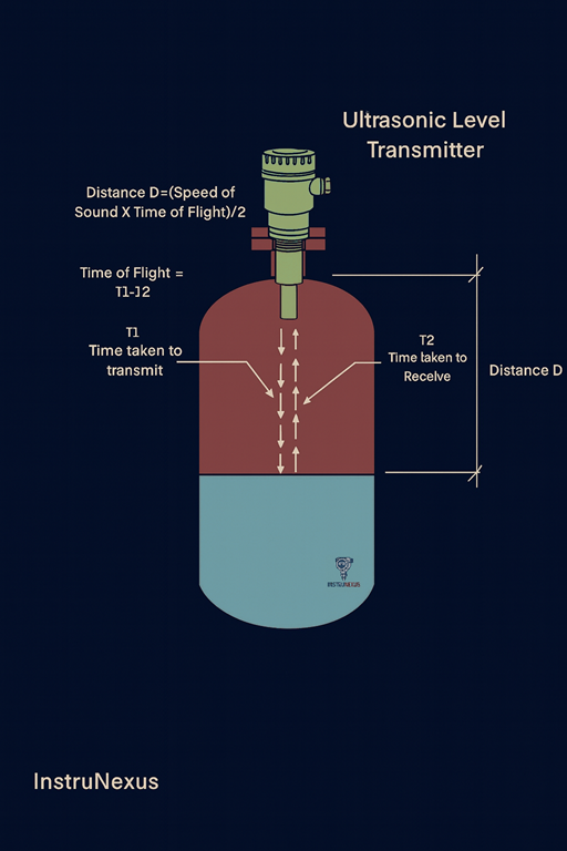
2.3.1 The Acoustic Time-of-Flight Principle
The operating principle of an ultrasonic transmitter is analogous to radar’s ToF but uses sound waves instead of electromagnetic waves. An ultrasonic transducer, typically mounted at the top of the vessel, generates a short pulse of high-frequency sound (a mechanical wave, usually between 20 kHz and 200 kHz). This sound pulse travels through the gas or vapor in the headspace until it strikes the surface of the process material, where it is reflected back to the transducer as an echo. The transmitter’s electronics measure the time elapsed between the emission of the pulse and the reception of the echo. The distance to the surface is then calculated using the formula:
The division by two is necessary because the measured time represents the round trip of the sound pulse.
2.3.2 Environmental Sensitivities
The critical distinction between ultrasonic and radar technology lies in the nature of the energy wave used. As mechanical waves, ultrasonic pulses require a medium (such as the gas in the headspace) for transmission and are therefore not suitable for vacuum applications. Furthermore, the speed of sound is not a universal constant but is highly dependent on the properties of the transmission medium. This makes ultrasonic measurement susceptible to several environmental factors:
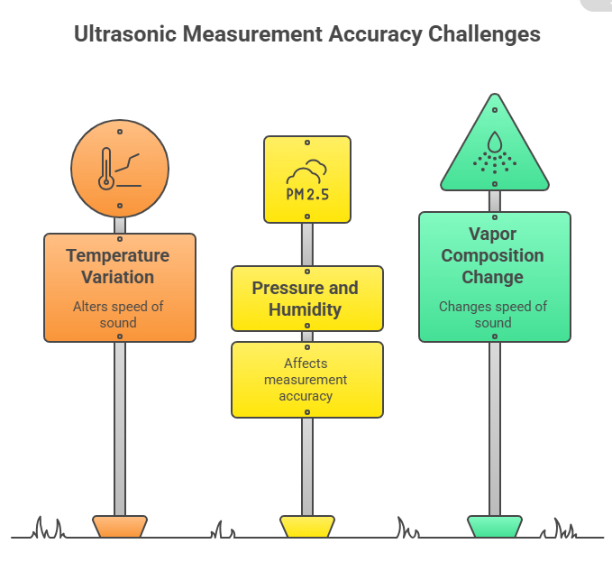
Temperature: This is the most significant factor affecting the speed of sound in air. A change in temperature will alter the speed of sound and introduce a measurement error if not compensated for. Most modern ultrasonic transmitters include an integrated temperature sensor to automatically correct for this effect.
Pressure and Humidity: Changes in the pressure or humidity of the headspace gas also alter the speed of sound and can affect measurement accuracy.
Vapor Space Composition: Perhaps the most significant limitation is that any change in the composition of the gas or vapor in the headspace will change the speed of sound. This makes ultrasonic technology unreliable in applications with volatile liquids or where the vapor composition varies.
2.3.3 Performance Analysis, Advantages, and Limitations
Advantages: Ultrasonic technology is a proven, reliable, and cost-effective solution for many non-contact level measurement applications. It is simple to install and commission. Since the measurement relies on a physical reflection, it is unaffected by material properties such as color, transparency, or dielectric constant. It is also a popular choice for open channel flow measurement in the water and wastewater industry.
Limitations: The performance of ultrasonic sensors is severely hampered by process conditions that can absorb or scatter the sound wave. These include the presence of heavy foam, dust, turbulence, or vapors. The technology requires a clear, unobstructed path to the material surface. Condensation or material buildup on the face of the transducer can block the signal, although some advanced models incorporate automatic self-cleaning features to mitigate this. Due to their environmental sensitivities, they are generally not recommended for pressurized vessels or applications with changing vapor spaces.
2.4 Displacer Level Transmitters: Buoyancy-Based Measurement
Displacer level transmitters are a robust, contact-based technology that has been a mainstay in the process industries for many years, particularly in challenging hydrocarbon applications. They operate on a principle of buoyancy to provide a reliable and accurate level or interface measurement.
![]()
2.4.1 Applying Archimedes’ Principle
The operation of a displacer transmitter is based on Archimedes’ principle, which states that the buoyant force exerted on a body immersed in a liquid is equal to the weight of the liquid it displaces. The sensing element is a weighted, cylindrical displacer of a specific length, designed to sink in the process liquid. As the liquid level rises and submerges more of the displacer, the buoyant force acting on it increases. This increased buoyant force results in a corresponding and proportional decrease in the displacer’s apparent weight. The transmitter measures this change in apparent weight to infer the liquid level.
2.4.2 Mechanical Designs: Torque Tube vs. Spring-Operated
The primary difference between types of displacer transmitters lies in the mechanical mechanism used to translate the change in the displacer’s apparent weight into a measurable signal.
Torque Tube: In this traditional design, the displacer is suspended from a cantilever arm that is attached to a hollow torque tube. As the displacer’s apparent weight changes, it applies a torsional force to the tube, causing it to twist slightly. A rod inside the hollow tube rotates with this twisting motion, and this angular displacement is converted into a proportional level signal. While this design is proven and has a vast installed base, it relies on a critical knife-edge bearing that is a point of friction and wear, requiring regular maintenance to ensure continued accuracy.
Spring-Operated: In more modern designs, the displacer is hung directly from a precision-calibrated range spring or coil. The change in apparent weight causes the spring to extend or contract in a linear motion. This vertical movement is often detected by a non-contact Linear Variable Differential Transformer (LVDT), which converts the core’s position into a highly accurate level signal. These spring-operated instruments overcome many of the issues of torque tubes; they are generally more robust, more accurate, more resistant to vibration, and require significantly less maintenance.
2.4.3 Performance Analysis, Advantages, and Limitations
Advantages: Displacer technology is simple, highly reliable, and accurate, making it a preferred choice for difficult applications in the hydrocarbon and chemical industries. It is exceptionally well-suited for operation at high process temperatures and pressures where other technologies may fail. One of its key strengths is its ability to accurately measure the interface level between two immiscible liquids with different densities. The measurement is also largely unaffected by process turbulence or pressure fluctuations.
Limitations: As a mechanical, contact-based technology, displacers are subject to wear and require periodic maintenance, particularly the torque tube design. The most significant limitation is its dependence on a constant liquid density. Since the measurement is based on buoyant force, any change in the specific gravity of the process liquid will cause a direct measurement error. The displacer element is also susceptible to buildup or coating from solids in the process fluid, which will alter its effective weight and lead to inaccurate readings. Finally, these instruments can be relatively bulky and expensive compared to other technologies.
2.5 Other Continuous Measurement Technologies
While DP, radar, ultrasonic, and displacer technologies are the most common, several other principles are employed for continuous level measurement in specific applications.
2.5.1 Capacitance Transmitters
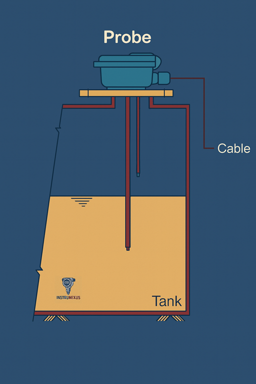
Capacitance level measurement operates by treating the sensor probe and the vessel wall as the two plates of a capacitor. The material between them—a combination of the process medium and the headspace vapor—acts as the dielectric. The principle relies on the fact that the process material will have a significantly different dielectric constant than the air or vapor in the headspace. As the level of the material rises, it displaces the low-dielectric vapor, causing the total capacitance of the system to change in direct proportion to the level.![]()
Performance: This technology is versatile, capable of measuring both conductive and non-conductive liquids, as well as powders and granular solids. For conductive liquids, the probe is coated with an insulating material (like PTFE), and the conductive liquid itself effectively becomes the outer plate of the capacitor. The primary limitation of capacitance technology is its dependence on a stable dielectric constant of the process material; any changes in moisture content, temperature, or material composition can alter the dielectric constant and cause measurement errors. The probe is also susceptible to errors from material buildup and coating.
2.5.2 Radiometric (Gamma) Systems
Radiometric level measurement is the ultimate non-contact, non-invasive technology, often considered the solution of last resort for the most extreme process conditions. The system consists of a low-intensity radioactive source (typically Cesium-137 or Cobalt-60) in a shielded holder on one side of the vessel and a sensitive detector on the opposite side. The source emits a focused field of gamma radiation that passes through the vessel walls and the process medium. The material inside the vessel attenuates, or absorbs, this radiation. As the level of the material rises, more radiation is blocked, and the intensity of the signal reaching the detector decreases. The detector measures this radiation intensity, which is inversely proportional to the material level.
![]()
Performance: Because the entire system is mounted externally, it is completely unaffected by harsh process conditions such as extreme temperatures and pressures, abrasive or corrosive media, high viscosity, internal agitators, or severe buildup. This makes it uniquely capable of providing reliable measurements where all other technologies would fail. Its primary disadvantages are its very high cost and the significant regulatory burden associated with purchasing, handling, and licensing radioactive materials.
2.5.3 Laser Transmitters
Laser level transmitters operate on the same Time-of-Flight principle as radar and ultrasonic sensors, but they use a highly focused beam of light. The transmitter emits a short pulse of laser light, which reflects off the material surface and returns to a detector. The transit time is measured to calculate the distance to the surface.
![]()
Performance: The key advantage of laser technology is its extremely narrow beam divergence (often less than 0.3 degrees). This allows it to be aimed with pinpoint accuracy, making it ideal for measuring level in narrow vessels, tanks with numerous internal obstructions, or for targeting specific areas on a solids pile. It can provide very fast and accurate measurements for both solids and liquids, including transparent and highly reflective liquids where other optical methods might fail. The main limitation is that the laser beam can be scattered or blocked by heavy dust, fog, or foam in the vapor space.
The evolution of these varied technologies reveals a clear and consistent trajectory within the process instrumentation field. There is a discernible progression from purely mechanical systems, such as torque tube displacers, toward more reliable solid-state electronic solutions like spring-operated LVDT displacers, which minimize wear points and maintenance needs.
A parallel trend is the shift from contact-based methods, with their inherent risks of corrosion and buildup, to non-contact technologies like radar and ultrasonic, which offer greater longevity and safety in harsh environments. This advancement culminates in the development of “smart” instruments.
Modern transmitters, particularly in the radar family, have moved beyond simple analog outputs to incorporate sophisticated signal processing, onboard diagnostics, and digital communication protocols. Features such as automatic echo tracking and filtering allow these devices to intelligently distinguish the true material level from process noise, such as agitator blades or internal structures, significantly reducing the commissioning and maintenance burden on technicians.
This overarching trend demonstrates an industry-wide drive to create more resilient, less invasive, and more intelligent instrumentation capable of providing reliable data with minimal human intervention, even in the most challenging process conditions.
Section 3: Point Level Detection Technologies
While continuous transmitters provide detailed level data, many applications only require a simple, discrete indication of whether a material has reached a specific high or low point. For these tasks, which include overfill alarms, pump control, and safety interlocks, point level switches offer a reliable and cost-effective solution.
3.1 Vibrating Fork Switches: The Universal Point Level Solution
Vibrating fork level switches have become one of the most popular and versatile technologies for point level detection in both liquids and free-flowing solids.
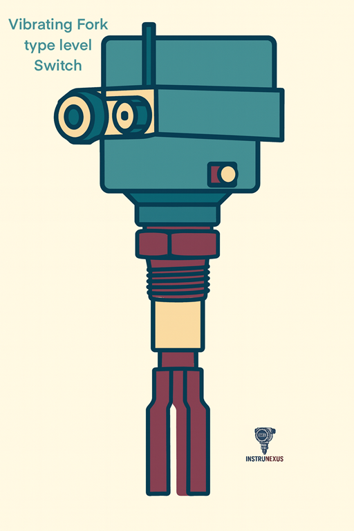
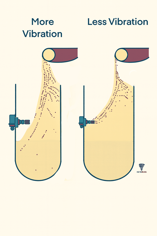
Principle of Operation: The sensor consists of a two-pronged tuning fork that is made to vibrate at its natural resonant frequency by a piezoelectric crystal. When the fork is in air (uncovered), it vibrates freely. When the process material covers the fork, the mass of the material dampens the vibration, causing a distinct change in the resonant frequency (for liquids) or a reduction in the amplitude of vibration (for solids). The onboard electronics detect this change and trigger a switch output (e.g., a relay).
Performance and Advantages: The primary advantage of vibrating fork technology is its exceptional reliability and broad applicability. The measurement is virtually unaffected by changing process conditions such as flow, turbulence, bubbles, foam, vibration, or variations in material properties like density, conductivity, or dielectric constant. This makes it a true “set it and forget it” solution for many applications. With no moving parts, the switches are virtually maintenance-free and do not require any calibration upon installation.
Limitations: The main limitation of vibrating fork switches is their unsuitability for use with very viscous liquids or sticky solids that can cause heavy material buildup. If the material is able to coat the forks to the extent that it forms a bridge between the tines, the switch will fail to detect the true level and will remain in a “wet” state even when the material level drops.
3.2 Other Point Level Switches
While vibrating forks are widely used, several other technologies are employed for point level detection in specific scenarios.
Capacitance/RF Admittance Switches: These operate on the same principle as continuous capacitance transmitters, detecting the change in capacitance as the material comes into contact with the probe. They are effective for both liquids and solids, and advanced RF admittance versions can offer immunity to buildup by compensating for the coating on the probe.
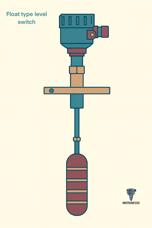
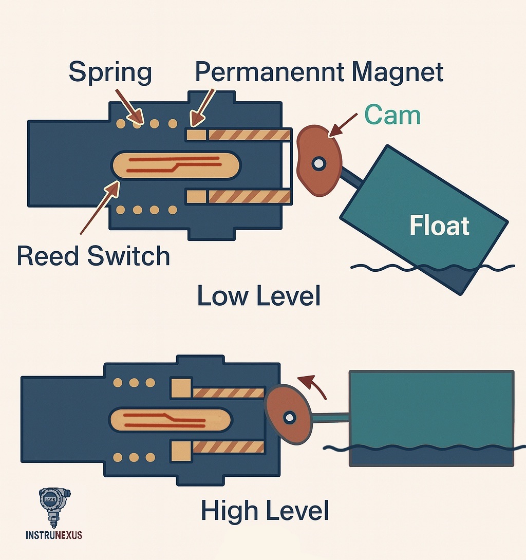
Float Switches: These are among the simplest and most cost-effective point level devices. A buoyant float containing a magnet rises and falls with the liquid level, actuating a sealed switch (typically a reed switch) in the stem as it passes. They are best suited for clean, non-viscous liquids where there is no risk of the float becoming stuck.
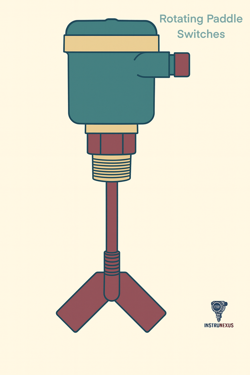
Rotating Paddle Switches: This is an established electromechanical technology used exclusively for bulk solids. A low-speed motor continuously turns a paddle. When the rising solid material physically obstructs and stalls the paddle’s rotation, the motor’s torque trips a microswitch, signaling that the level has been reached.
Conductive Switches: This technology is used for point level detection in conductive liquids, such as water. It employs two or more electrodes. When the rising liquid touches the electrodes, it completes an electrical circuit, which is detected by the electronics to actuate a switch.
Section 4: Comparative Analysis and Technology Selection Guide
Selecting the optimal level measurement technology from the vast array of available options can be a complex task. It requires a systematic evaluation of the application’s specific needs against the performance characteristics, strengths, and weaknesses of each technology. A successful selection balances performance requirements, process compatibility, and total cost of ownership.
4.1 Technology Selection Matrix
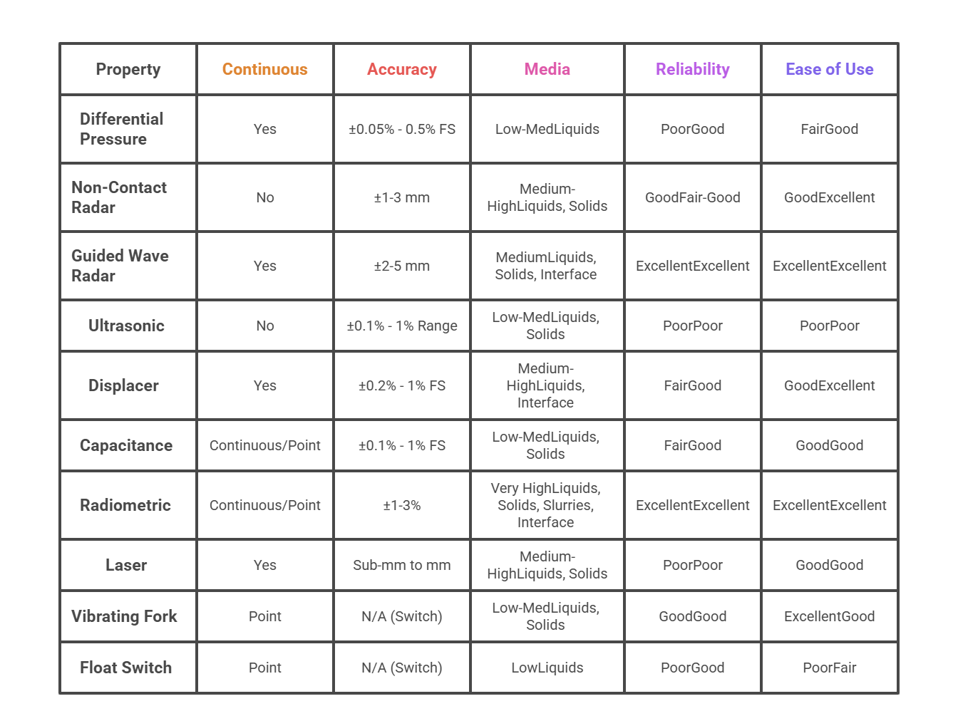
The decision-making process for choosing a level measurement instrument involves navigating numerous technologies and dozens of process variables. A structured comparison matrix serves as an invaluable tool for this process. It condenses complex technical information into a single, scannable reference, allowing for a rapid first-pass filtering of options. By presenting key performance indicators and suitability for common process challenges, it provides an at-a-glance framework that directly aligns with an engineer’s need to select the right technology for a specific application. The following table provides a comparative overview of the primary level measurement technologies discussed.
4.2 Performance Metrics:
4.2.1 Accuracy, Repeatability, and Range
The required accuracy of a measurement is a primary driver of technology selection and cost. It is crucial to understand how accuracy is specified for different technologies. For instance, DP and displacer transmitters often state accuracy as a percentage of their calibrated full scale (FS), meaning the absolute error is larger for a larger measurement range. In contrast, technologies like radar and laser often specify a fixed accuracy (e.g., ±2 mm) that is independent of the measurement range.
Applications requiring the highest precision, such as custody transfer for inventory accounting, often favor technologies with high inherent accuracy like radar, magnetostrictive, or servo gauges. For less critical applications, such as general tank monitoring, a lower accuracy may be perfectly acceptable.
4.2.2 Total Cost of Ownership (TCO)
A strategic evaluation must look beyond the initial purchase price to consider the total cost of ownership over the instrument’s lifecycle.
Initial Cost: Simple mechanical devices like float switches are the least expensive, while advanced technologies like radar and radiometric systems have the highest initial capital outlay.
Installation Costs: Non-contact sensors are often easier and faster to install than contact devices like DP transmitters, which may require multiple vessel penetrations and extensive impulse piping.
Maintenance and Longevity: This is where the TCO analysis becomes critical. Non-contact sensors, having no moving parts and no exposure to the process medium, typically require minimal maintenance and offer a long service life, resulting in a lower TCO despite a higher initial cost. Conversely, contact sensors like DP transmitters with impulse lines or mechanical displacers may have a lower purchase price but incur significant ongoing maintenance costs related to cleaning, recalibration, and repair of wetted parts, especially in harsh services.
4.3 Application Suitability: Media and Interfaces
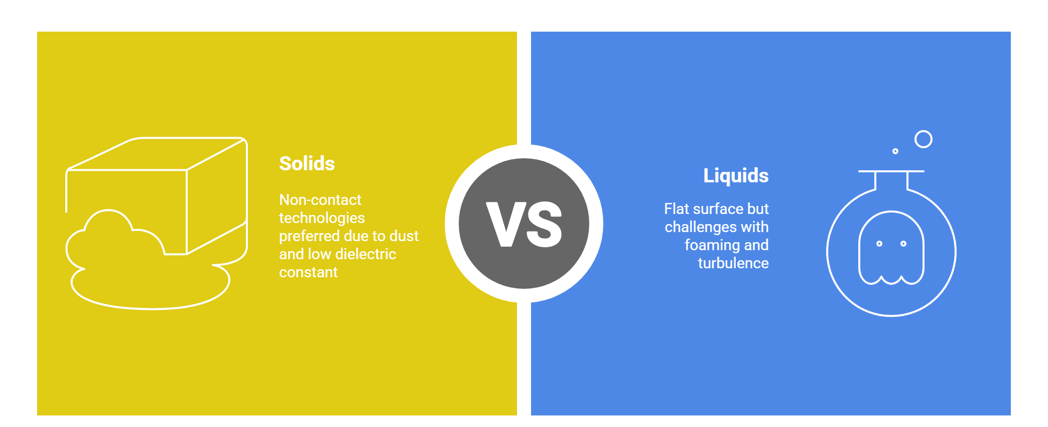
4.3.1 Liquids vs. Solids
The physical state of the material being measured presents distinct challenges.
4.3.2 Interface Detection
Measuring the interface between two immiscible liquids is a specialized but critical application. The primary technologies suited for this task are Guided Wave Radar (GWR) and displacer transmitters. GWR works by detecting the reflections from both the upper liquid surface and the lower liquid-liquid interface, which requires a sufficient difference in the dielectric constants of the two liquids. Displacers work by sensing the change in buoyant force as the displacer element passes through the interface of two liquids with different densities.
4.4 Navigating Challenging Process Conditions
The process environment is often the deciding factor that dictates which technologies are viable and which are destined to fail.
4.4.1 Managing Foam, Vapors, and Dust
These conditions in the headspace can interfere with “through-air” measurement technologies.
Foam: Foam is a significant challenge for ultrasonic sensors, as the light, aerated structure of the foam absorbs the acoustic energy of the sound pulse, preventing it from reaching the actual liquid surface. Radar technology is far more robust; the electromagnetic waves can typically penetrate most foam layers to measure the liquid level beneath. Guided Wave Radar is particularly effective, as the signal is guided by the probe and is less susceptible to being scattered by the foam.
Vapors and Dust: Heavy vapors can alter the speed of sound, causing significant errors in ultrasonic measurements. Heavy dust can scatter both ultrasonic and laser signals, leading to a loss of signal or inaccurate readings. Radar is less affected by dust and vapors, although very dense dust clouds or saturated steam can attenuate the signal, especially at higher frequencies. For the most extreme dust or vapor conditions, GWR and Radiometric systems offer the highest reliability.
4.4.2 Overcoming Turbulence and Agitation
A turbulent or agitated liquid surface does not provide a stable target for reflection, posing a challenge for non-contact technologies.
The fluctuating surface can scatter the signals from Ultrasonic and Non-Contact Radar transmitters, leading to unstable or lost readings. DP transmitter readings will become very “noisy” and require electronic damping in the transmitter, which can slow the instrument’s response to real level changes.
Contact technologies like Displacers and Vibrating Forks are generally robust and unaffected by turbulence. Guided Wave Radar excels in these conditions because the signal is guided along the probe and does not rely on a clean reflection from a calm surface. An alternative engineering solution for many technologies is to install the sensor in an external bypass chamber or an internal stilling well, which provides a calm liquid surface for measurement that is representative of the main vessel level.
4.4.3 Solutions for Extreme Temperatures and Pressures
High temperatures and pressures can exceed the operating limits of many electronic and mechanical instruments.
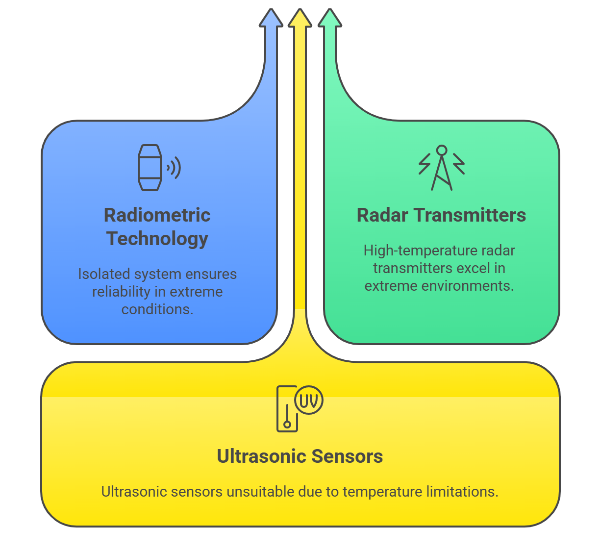
Radiometric technology is the ultimate solution for extreme conditions, as the entire measurement system is mounted outside the vessel and is completely isolated from the process.
Displacers and specially designed Radar transmitters (both GWR and NCR) are also capable of operating at very high temperatures (up to 450°C / 850°F) and pressures.
Ultrasonic sensors, by contrast, have much stricter temperature and pressure limitations, making them unsuitable for such applications.
4.4.4 Material Considerations: Corrosive and Abrasive Media
When the process material is chemically aggressive or abrasive, instrument longevity is a primary concern.
Non-contact technologies (Radar, Ultrasonic, Laser, Radiometric) are inherently superior choices, as they avoid any physical contact with the hostile medium.
For contact technologies, careful material selection is critical. Wetted parts such as probes, diaphragms, and displacers can be constructed from corrosion-resistant exotic alloys like Hastelloy or Titanium, or they can be coated with inert polymers like PTFE or PFA to protect them from chemical attack. Abrasive solids can physically wear down contact probes over time, making non-contact measurement a more reliable long-term solution.
Section 5: Industrial Applications and Strategic Recommendations
The theoretical principles and performance characteristics of level measurement technologies are best understood when grounded in the context of real-world industrial applications. The optimal choice of instrument is always a function of the specific challenges and requirements of the process and industry in which it will be deployed.
5.1 Case Studies by Industry
Different industries present unique sets of challenges that favor certain level measurement technologies.
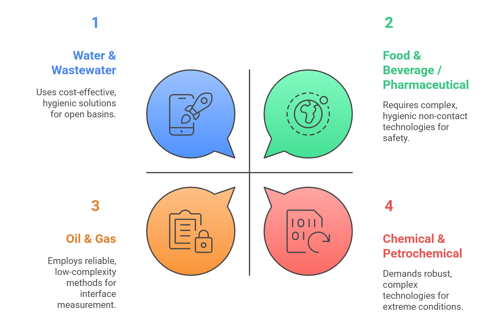
Chemical & Petrochemical: This sector is characterized by a wide range of process conditions, including extreme temperatures and pressures, and the presence of highly corrosive, toxic, and hazardous materials. Consequently, robust and safe measurement is paramount. Non-contact technologies like Radar are highly favored for their chemical resistance and reliability in harsh vapor spaces. For the most extreme applications, Radiometric systems are often employed. Displacer transmitters also have a large historical installed base, particularly in older hydrocarbon processing units, due to their proven reliability at high temperatures and pressures.
Oil & Gas: Similar to the chemical industry, oil and gas applications involve high pressures, high temperatures, and hazardous materials. A unique and critical requirement is the frequent need for accurate interface measurement to distinguish between oil, water, and emulsion layers in separators and storage tanks. Guided Wave Radar (GWR) has become a dominant technology in this area due to its exceptional ability to measure both the overall level and the oil/water interface simultaneously. Differential Pressure transmitters are also widely used for general level applications throughout the industry.
Water & Wastewater: Applications in this industry often involve large, open basins, channels, and sumps at atmospheric pressure. Ultrasonic technology has traditionally been a popular, cost-effective choice for these applications. However, the presence of foam and scum on the water surface can challenge ultrasonic sensors. As a result, non-contact Radar is rapidly gaining market share, as its cost has decreased and its performance in these conditions is superior.
Food & Beverage / Pharmaceutical: In these industries, hygienic design is the most critical requirement to prevent product contamination and ensure compliance with regulatory standards (e.g., FDA, 3-A). Non-contact technologies like Radar and Ultrasonic are often preferred. When contact sensors are used, they must have sanitary process connections (e.g., Tri-Clamp) and be constructed from highly polished, food-grade materials like 316L stainless steel. Vibrating fork switches and capacitance probes are commonly available in such hygienic configurations.
5.2 Strategic Selection Framework: A Step-by-Step Guide
A systematic approach is essential to ensure the selection of the most appropriate and cost-effective level measurement solution. The following framework, which synthesizes best practices from engineering guides, provides a logical decision-making process.
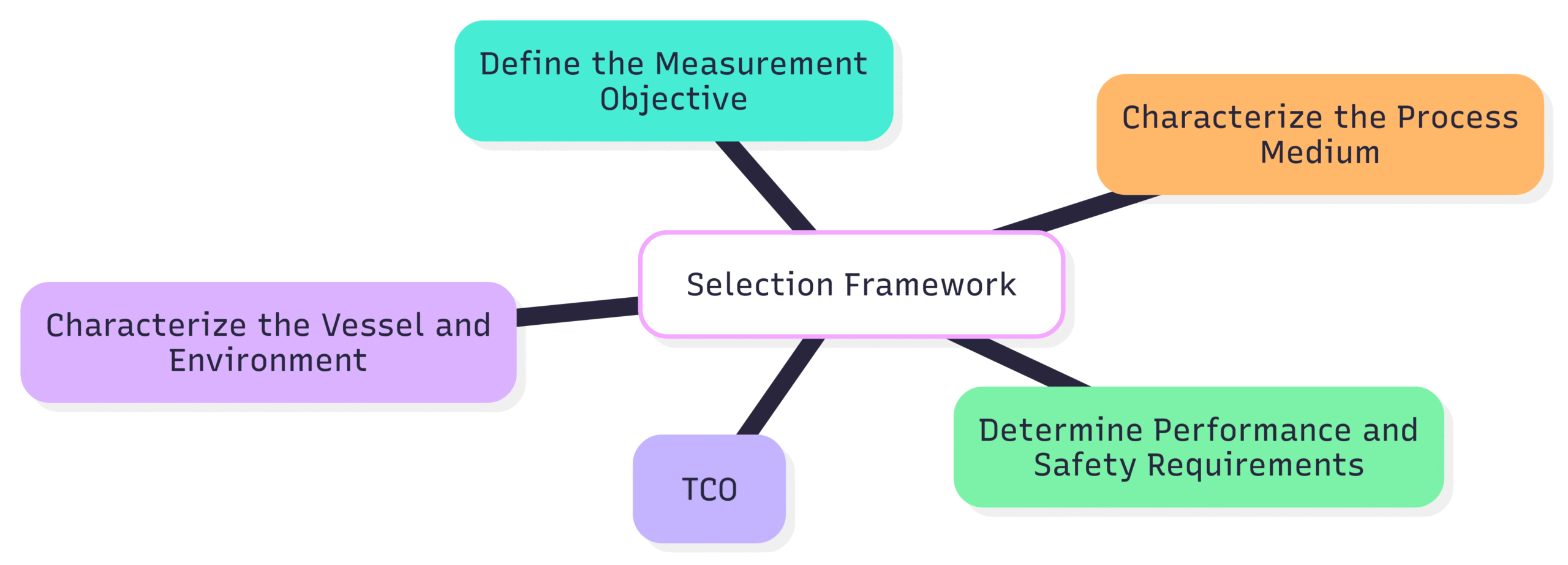
Step 1: Define the Measurement Objective.
Is the primary need for continuous measurement (for process control, inventory), point level detection (for alarms, pump control), or interface measurement?
What is the purpose of the measurement? Is it for basic operational monitoring, or is it a critical safety function (e.g., overfill prevention) or for custody transfer (requiring high accuracy)?
Step 2: Characterize the Process Medium.
What is the state of the material: liquid, bulk solid, or slurry?
What are its key physical and chemical properties?
For liquids: What is the density/specific gravity, viscosity, and dielectric constant? Are these properties stable or do they vary with temperature or batch?
For solids: What is the particle size, bulk density, and angle of repose?
Is the medium corrosive, abrasive, sticky, or prone to coating the sensor?
Step 3: Characterize the Vessel and Environment.
What are the minimum and maximum operating temperature and pressure?
Are challenging conditions such as foam, heavy dust, dense vapors, or severe agitation/turbulence present?
What is the vessel’s geometry (height, diameter, shape) and material of construction?
Are there internal obstructions such as agitators, heating coils, baffles, or ladders that could interfere with the measurement?
What are the details of the available process connection (nozzle size, type, and location)?
Step 4: Determine Performance and Safety Requirements.
What is the required accuracy and repeatability for the application?
Are there specific safety requirements, such as a Safety Integrity Level (SIL) rating for a safety instrumented system (SIS)?
Is the installation in a hazardous area requiring explosion-proof or intrinsically safe approvals (e.g., ATEX, IECEx)?
Step 5: Evaluate Total Cost of Ownership (TCO).
Balance the initial instrument purchase price against the costs of installation, commissioning, calibration, and long-term maintenance. A cheaper initial solution may prove more expensive over its lifetime if it requires frequent cleaning, recalibration, or replacement in a challenging application.
5.3 Future Trends in Level Measurement Technology
The field of level measurement is continually evolving, driven by the demands of modern industry for greater efficiency, safety, and data integration. Several key trends are shaping the future of this technology.
The primary trajectory is away from simple sensors that provide a single data point and towards intelligent edge devices. This evolution is transforming the level transmitter from a basic process sensor into a strategic asset for plant-wide optimization. Modern instruments are increasingly equipped with advanced diagnostics that monitor not only the process level but also their own internal health and the quality of the measurement itself.
For example, a radar transmitter can provide not just the level reading, but also data on the signal strength of the echo, which can indicate potential issues like antenna coating or excessive foam long before a measurement failure occurs.
This rich stream of primary, secondary, and diagnostic data can be transmitted via digital communication protocols to higher-level plant asset management and predictive maintenance systems. This enables a shift in maintenance strategies from a reactive or scheduled approach to a proactive, predictive model, where potential instrument failures are identified and addressed before they can impact the process.
Other significant trends include:
Increased Connectivity: The adoption of wireless communication protocols like WirelessHART and the integration of level sensors into the Industrial Internet of Things (IIoT) are becoming more common. This allows for remote monitoring of assets in difficult-to-access locations and provides a wealth of data for plant-wide analytics without the cost of extensive wiring.
Technology Convergence and Enhancement: The performance gap between different technologies is narrowing. Non-contacting radar, for example, is now equipped with such advanced signal processing that it can handle many of the turbulent or foamy applications that once required the use of guided wave radar. Similarly, GWR is being enhanced with features like dynamic vapor compensation to improve its accuracy in high-pressure steam applications.
Cost Reduction and Miniaturization: Ongoing research and development continue to make advanced technologies, particularly radar, more compact and affordable. This is accelerating their adoption in mainstream applications that were previously the domain of simpler, less robust technologies like ultrasonic or mechanical floats.