
Mastering the 3D 30% Model Review: A Comprehensive Checklist for Instruments and Cabling
In the world of large-scale industrial projects, success is forged in the details. Before a single pipe is welded or a foundation is poured, the entire plant exists as a complex digital twin: the 3D model. One of the most critical milestones in this digital phase is the 30% model review. This isn’t just a progress check; it’s the foundational quality gate that prevents catastrophic budget overruns and schedule delays.
Getting this review right means your project is built on solid ground. Getting it wrong means facing costly rework, clashes, and operational nightmares down the line. This comprehensive guide will walk you through everything you need to know to conduct a successful 30% model review, with a specific focus on the often-overlooked but vital details of instrumentation, control systems, and cable routing.
Ready to build a robust, operable, and maintainable plant from the ground up? Let’s dive in.
What Exactly is a 3D 30% Model Review?
The “30%” milestone can be misleading. It doesn’t mean that 30% of the total engineering work is complete. Instead, it signifies a specific level of design maturity. At this stage, the following elements are typically finalized and ready for review:
Final Plot Plan: The overall layout of the facility is fixed.
Major Equipment Locations: All primary equipment (vessels, pumps, compressors, columns) are placed in the model with their final dimensions and nozzle orientations.
Main Pipe Racks and Primary Piping: The main arteries of the plant’s piping system are routed.
Structural Concepts: The primary steel structures supporting racks and equipment are modeled.
Preliminary P&IDs: The Process and Instrumentation Diagrams are issued for design and form the basis of the review.
The purpose of the 30% review is to get a multi-disciplinary buy-in on this layout before the project moves into the far more detailed and resource-intensive subsequent phases. It’s the “speak now or forever hold your peace” moment for the plant’s physical layout.
A successful review process involves a structured flow of information and collaboration.
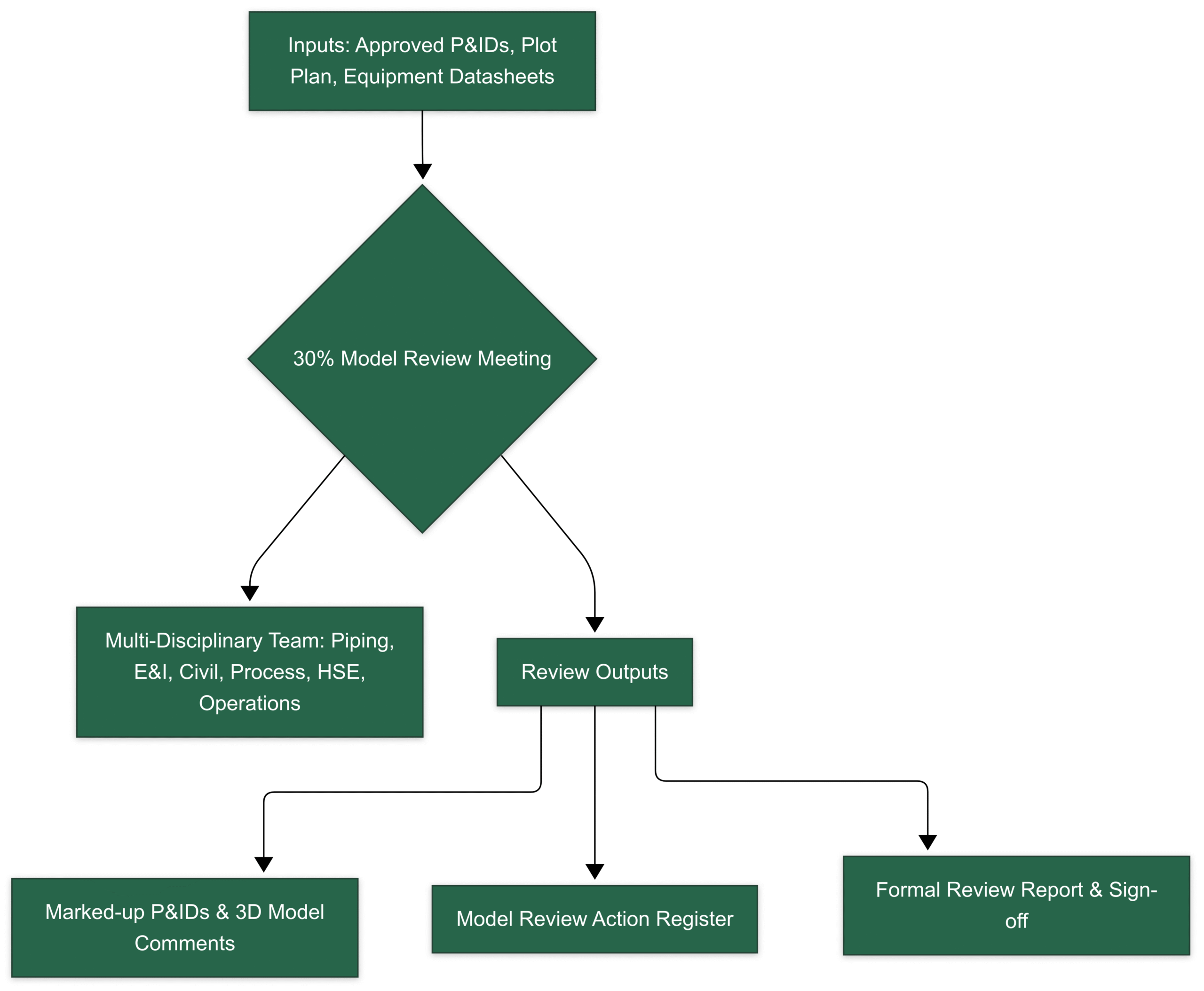
The core objective is to validate the design’s safety, operability, and maintainability.
The Instrumentation & Control (I&C) Deep Dive: A Detailed Checklist
While the 30% review covers all disciplines, the I&C and Electrical scope is where small oversights can lead to major operational headaches. An instrument that can’t be maintained, a gauge that can’t be read, or a valve that can’t be accessed are all symptoms of a poor review.
Here’s a detailed checklist broken down by equipment type.
Flow Instruments (Meters, Orifice Plates, etc.)
Accurate flow measurement is the bedrock of process control. Improper installation is the number one cause of inaccurate readings.
Key Checks:
Tagging and Location: First, the basics. Does the tag number in the model match the P&ID? Is the instrument located in the correct pipeline and at the correct position shown on the P&ID?
Upstream & Downstream Straight Lengths: This is the most critical check for flow meters like orifice plates, vortex, ultrasonic, and turbine meters. These devices require a stable, non-turbulent flow profile to work correctly.
Verify: Check for a sufficient length of straight, unobstructed pipe before (upstream) and after (downstream) the flow element.
Rule of Thumb: A common starting point is 10 pipe diameters (10D) upstream and 5 pipe diameters (5D) downstream, but always refer to the specific vendor requirements and project standards (e.g., API, AGA). The 3D model is the only place to verify this in three dimensions.
Orientation:
Magnetic Flow Meters: Are the electrodes on the horizontal axis to avoid measuring air at the top or sediment at the bottom of the pipe? The pipe should be flowing full.
Coriolis Meters: Is the meter oriented to be self-draining for the specific service (liquid or gas)?
Orifice Plates: For gas service, is the drain hole correctly oriented at the bottom? For liquid service, is the vent hole at the top?
Accessibility for Maintenance: Can a technician safely access the transmitter for calibration? Is there enough physical space to remove the entire meter body from the line? For insertion-style meters, is there clearance to retract the probe?
Proximity to Disturbances: Ensure the meter isn’t placed immediately after a control valve, pump outlet, or a series of bends that can introduce swirl and turbulence, even if the straight-length requirement is met.
Level Instruments (Transmitters, Gauges, Switches)
From ensuring vessel inventories to preventing dangerous overfills, level instruments are critical for both control and safety.
Key Checks:
Visibility of Level Gauges: For Magnetic Level Indicators (MLIs) and armored glass gauges, the check is simple: can an operator standing on the designated grade or platform clearly read the level? The model review is the perfect time to “stand” in the operator’s shoes and check sightlines. Ensure the gauge isn’t facing a column or another pipe.
Nozzle Locations and Elevations:
DP Transmitters: Verify the high-pressure (HP) and low-pressure (LP) tapping nozzles on the vessel match the P&ID and datasheet. The elevations are critical for calculating the correct level range.
Radar/Ultrasonic: The instrument’s nozzle should provide a clear, unobstructed “view” of the liquid surface. Check for interferences inside the tank, such as inlet pipes, agitator blades, or structural baffles, which can create false echoes. If needed, is a stilling well correctly modeled?
Bridles and External Chambers: For instruments mounted on external chambers or bridles:
Accessibility: Can maintenance access the isolation valves, drain valves, and the instruments themselves?
Layout: Is the chamber properly supported? Is there sufficient space around it for maintenance activities?
Clearance for Removal: For top-mounted instruments like Guided Wave Radar (GWR) or displacer-type transmitters, is there enough overhead clearance to lift the entire probe or element out of the vessel nozzle? This is a frequently missed check that can lead to major rework.
Pressure Instruments (Transmitters, Gauges, Switches)
Pressure instruments are numerous and often seem simple, but their placement is key to safe and efficient operations.
Key Checks:
Gauge Readability: Similar to level gauges, pressure gauges must be easily readable from the normal operating position.
Position: Are they located at a reasonable height (typically 1.2m to 1.5m from the platform)?
Orientation: Is the dial face oriented towards the operator, not facing upwards, downwards, or into a structure?
Transmitter Accessibility: Can a technician easily hook up a calibrator to the transmitter? Is the local digital display (if any) visible? Is there access to the instrument’s isolation valve manifold (block-and-bleed valves)?
Tapping Point Location:
Gas/Vapor Service: Tapping points should be on the top or side of the pipe to prevent condensate from filling the impulse line and causing errors.
Liquid Service: Tapping points should be on the side of the pipe to avoid collecting sediment (from the bottom) or trapped gas (from the top).
Protection from Damage: Are instruments located away from high-traffic areas, forklift paths, or ladders where they could be accidentally damaged?
Temperature Instruments (Thermowells, RTDs, Thermocouples)
Temperature is a primary process variable, and getting a representative reading is essential.
Key Checks:
Immersion Length: The thermowell must be inserted deep enough into the process flow to get an accurate reading, away from the influence of the pipe wall temperature.
Verification: The tip of the thermowell should ideally be in the middle third of the pipe’s internal diameter.
Check: Does the model show a thermowell that is long enough for the specified pipe size?
Clearance for Removal: Is there enough straight, unobstructed space to pull the entire thermowell assembly out of the nozzle for inspection or replacement? This requires a clear space equal to the full length of the thermowell plus some working room.
Orientation: On pipe elbows, thermowells should be installed against the direction of flow for better measurement. In horizontal pipe runs, they should be installed in a way that the sensing element remains wetted (e.g., installed from the side, not the top).
Wake Frequency Calculation (WFC) Consideration: While the detailed WFC is a separate engineering calculation, the 3D model review is a chance for a sanity check. Extremely long, unsupported thermowells in high-velocity flows are a red flag for potential vibration-induced failure. The model should reflect a design that is likely to pass the WFC.
Control Valves
Control valves are the “muscles” of the control system. If they can’t be maintained, the process can’t be controlled.
Key Checks:
MAINTENANCE, MAINTENANCE, MAINTENANCE: This is the single most important check for control valves.
Actuator Removal: Is there a clear path to remove the actuator? For large valves, is there a designated drop zone and access for a crane or chain block?
Body Removal: Can the entire valve body be unbolted and removed from the pipeline?
Access: Can a technician get to the positioner, air filter regulator, and I/P converter?
Handwheel Accessibility: Can an operator safely access and operate the manual handwheel on the actuator, even if it’s just for emergency use? Is there enough leverage? Is it at a safe height?
Actuator Orientation: The actuator is often the bulkiest part of the assembly. Is it oriented to avoid clashes with adjacent piping, steelwork, or cable trays? This is a common source of clashes found in later design stages.
Bypass and Isolation: Is the layout of the block and bypass valves logical? Are their handwheels accessible and not interfering with each other?
Support: Large control valve assemblies are heavy. Verify that they are adequately supported to prevent stress on the connecting pipes.
On-line Analyzers
Analyzers provide critical quality data but are complex systems requiring careful planning.
Key Checks:
Analyzer Shelter/Rack Location:
Safety: Is it located in a safe area, considering the hazardous area classification?
Proximity: Is it located as close as reasonably possible to the sample take-off point to minimize time delay in the sample loop?
Access: Is there vehicle and personnel access to the shelter for maintenance and delivery of consumables (e.g., calibration gas cylinders)?
Sample Take-Off Point: Is the tap located to extract a representative sample of the process fluid, avoiding dead zones or unmixed streams?
Sample Transport Lines: The 30% model should reserve a routing corridor for the sample transport lines (the “fast loop”). Check that this route is feasible and doesn’t create pockets where liquids or solids could settle. Consider if heat tracing will be required and if there is space for it.
Utilities: Has space been allocated for all required analyzer utilities? This includes instrument air, power, nitrogen, water for cooling, and a route for vent and drain lines to a safe location. This is often forgotten at the 30% stage.
Shelter Layout: Has a preliminary internal footprint been allocated for the analyzer, sample conditioning system (SCS), and calibration gas bottles? There must be sufficient space for a technician to work safely inside.
The Backbone: Cable Routing & Management
Cables are the nervous system of the plant. A well-designed routing philosophy at the 30% stage prevents chaos later.
Key Checks:
Main Cable Highways: Are the primary cable tray routes from the main electrical substations (MES) and instrument rack rooms (IRR) to the unit areas defined? These are major space consumers and must be coordinated early.
Segregation Philosophy: This is a critical safety and signal integrity check. The model must show a clear and consistent strategy for separating different types of cables to prevent electromagnetic interference (EMI) and faults from cascading.
High Voltage (HV) vs. Low Voltage (LV) Power: Must be in separate trays.
Power vs. Control/Instrumentation: Must be in separate trays. A specified minimum distance between trays should be maintained.
Analog vs. Digital vs. Fiber Optic: Critical instrumentation signals (e.g., 4-20mA) should be routed separately from noisy digital signals or power cables.
Junction Box (JB) Locations: Are the preliminary locations for instrument JBs identified?
Accessibility: Are they mounted at a reasonable height for termination work (not too high, not too low)?
Centralization: Are they placed in a logical location to collect signals from nearby instruments, minimizing the length of individual field cables?
Safety: Are they located outside of areas with a high risk of physical damage?
Underground vs. Aboveground: Has the project defined the philosophy for main cable routes? If underground duct banks are used, has the space and routing corridor been reserved and checked for clashes with foundations and underground piping?
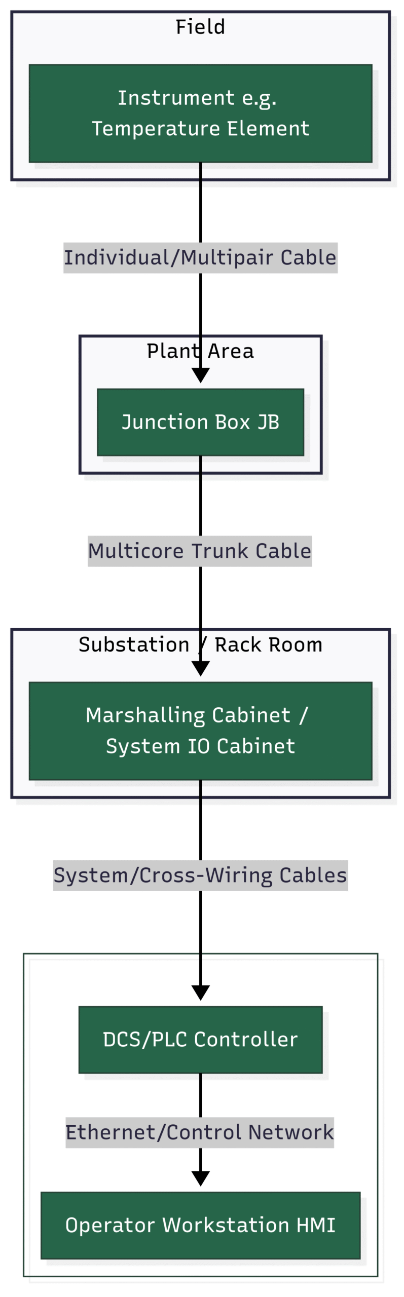
The flow of data from the field to the control room follows a distinct hierarchy that the cable routing must support.
Conclusion: Measure Twice, Build Once
The 3D 30% model review is far more than a simple checkbox exercise. It is a strategic investment of engineering hours that pays massive dividends. By thoroughly vetting the layout for safety, operability, and maintainability—with a sharp eye on the detailed requirements of instrumentation and cabling—you set the stage for a smoother, more efficient, and ultimately more successful project.
Embrace the 3D model as a collaborative tool. Walk through it, question everything, and imagine yourself as the operator or technician who will live with the design for the next 30 years. A well-executed 30% review is the single best tool you have to turn a digital dream into a functional reality.
I think It is better to mention the difference between junction boxes.
They are classified by **safety** (IS for hazardous areas, Non-IS for safe areas).
They are also classified by **signal type** (Analog for transmitters, Digital for switches).
This gives four main categories: **IS Analog, IS Digital, Non-IS Analog, Non-IS Digital**, though some projects may combine them.