

Pressure Drop Calculation Across Instruments: Ace Your Interview with These Top 10 Q&As
In the world of process control and instrumentation, a thorough understanding of pressure drop is paramount for ensuring the efficiency, safety, and reliability of any system. For engineers and technicians, the ability to accurately calculate and interpret pressure drop across various instruments is a critical skill, making it a frequent topic in job interviews. Whether you’re a recent graduate or a seasoned professional, being prepared to discuss the nuances of pressure drop can set you apart. Here are the top 10 interview questions and answers to help you ace your next technical interview.
1. Why is understanding and calculating pressure drop across instruments so important?
Answer: This is a fundamental question that probes your understanding of the bigger picture. Your answer should highlight the multifaceted impact of pressure drop.
“Understanding and accurately calculating pressure drop is critical for several key reasons:
- Proper Instrument Sizing and Selection: Many instruments, like control valves and orifice plates, must be sized based on the pressure drop they will induce. An incorrect calculation can lead to the selection of an oversized or undersized instrument, resulting in poor control, reduced rangeability, and inefficiency.
- Energy Consumption: Pressure drop represents an energy loss in the system. Higher pressure drops require more energy from pumps and compressors to maintain the desired flow rate, leading to increased operational costs.
- Process Performance and Control: The pressure drop across a control valve is the driving force that allows it to manipulate the flow rate. Insufficient pressure drop can render a control valve ineffective, leading to a loss of process control. Conversely, excessive pressure drop can cause issues like cavitation and flashing.
- System Troubleshooting: Unexpected changes in pressure drop across an instrument are often an indicator of a problem, such as a clogged filter, a partially closed valve, or a damaged orifice plate. Monitoring pressure drop is a key diagnostic tool.
- Safety: In certain applications, excessive pressure drop can lead to pressures exceeding the design limits of upstream equipment, posing a safety risk.”
2. What is the difference between permanent and temporary pressure loss, particularly concerning an orifice plate?
Answer: This question tests your knowledge of fluid dynamics as it relates to common flow measurement devices.
“The distinction lies in how much of the initial pressure is recovered downstream of the instrument.
- Temporary Pressure Loss (or differential pressure) is the maximum pressure difference observed between the upstream high-pressure tap and the low-pressure tap at the vena contracta (the point of narrowest flow) of an orifice plate. This differential pressure is what is measured to infer the flow rate.
- Permanent Pressure Loss is the unrecoverable pressure drop that remains in the system after the fluid has passed through the orifice and the pressure has partially recovered downstream. It represents a permanent energy loss.
For an orifice plate, the permanent pressure loss is a significant fraction of the temporary pressure loss. This is because the sharp-edged orifice causes a high degree of turbulence and energy dissipation. Instruments like a venturi meter, with its more gradual converging and diverging sections, have a much lower permanent pressure loss for the same differential pressure, making them more energy-efficient.”
3. You are sizing a control valve. How do you determine the required pressure drop across it?
Answer: This practical question assesses your understanding of control valve sizing principles.
“Determining the required pressure drop for a control valve is a critical step in the sizing process and involves analyzing the overall system hydraulics. A common rule of thumb is that the pressure drop across the control valve should be a significant portion of the total dynamic pressure drop of the system it’s controlling.
Typically, the control valve should take at least 30% of the total friction losses in the system, or a minimum of 15 psi (1 bar), whichever is greater. This ensures that the valve has enough ‘authority’ to effectively regulate the flow without being overly sensitive.
The process involves:
- Calculating the total system pressure drop: This includes friction losses in pipes, fittings, heat exchangers, and any other equipment in the flow path at the desired flow rate, excluding the control valve.
- Determining the available pressure drop: This is the difference between the supply pressure and the required pressure at the destination, minus the total system pressure drop calculated in step 1. This available pressure drop is what can be allocated to the control valve.
- Evaluating for different flow scenarios: It’s crucial to analyze the pressure drop at minimum, normal, and maximum flow conditions to ensure the valve will perform effectively across its entire operating range.”
4. What are the consequences of an incorrectly calculated (too high or too low) pressure drop for a control valve?
Answer: This question delves into the practical implications of calculation errors.
“An incorrectly calculated pressure drop for a control valve can lead to significant operational problems:
If the calculated pressure drop is too low (and the valve is oversized):
- Poor Control: The valve will operate in a nearly closed position for most of its range, leading to a very sensitive response. Small changes in the controller output will cause large changes in flow, making the process difficult to control and prone to instability.
- Reduced Rangeability: The effective controllable flow range of the valve is diminished.
- Valve Wear: Operating near the seat can lead to erosion and damage to the valve trim.
If the calculated pressure drop is too high (and the valve is undersized):
- Inability to Achieve Maximum Flow: The valve may not be able to pass the required maximum flow rate, even when fully open, effectively starving the process.
- Cavitation and Flashing: High-pressure drops across a liquid service valve can cause the pressure to fall below the liquid’s vapor pressure, leading to the formation and collapse of vapor bubbles (cavitation) or the liquid turning into vapor (flashing). Both phenomena can cause severe damage to the valve and downstream piping, as well as generate significant noise and vibration.
- Increased Energy Costs: A higher pressure drop than necessary contributes to wasted energy.”
5. What is the fundamental formula for calculating pressure drop across an orifice plate, and what are the key parameters?
Answer: A direct question about a core formula. Be prepared to explain the components.
“The fundamental equation for calculating the volumetric flow rate through an orifice plate is derived from Bernoulli’s principle. The pressure drop is a key component of this calculation. The formula for the differential pressure () is implicitly part of the flow rate calculation, which is:
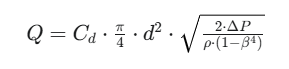
Where:
- is the volumetric flow rate.
- is the discharge coefficient, which is an empirically determined factor that accounts for the real-world effects of viscosity and velocity profile.
- is the diameter of the orifice.
- is the differential pressure across the orifice taps.
- is the density of the fluid.
- (Beta ratio) is the ratio of the orifice diameter to the pipe diameter ().
To directly calculate the pressure drop () for a given flow rate, you would rearrange this formula. The key takeaway is that the pressure drop is directly proportional to the square of the flow rate. This non-linear relationship is fundamental to how differential pressure flow meters work.”
6. What factors can affect the pressure drop across an instrument like a control valve or a filter?
Answer: This question assesses your broad understanding of the variables at play.
“Several factors can influence the pressure drop across an instrument:
- Flow Rate: For most instruments, the pressure drop increases with the square of the flow rate. This is the most significant factor.
- Fluid Properties:
- Density (): Higher density fluids will result in a higher pressure drop for the same flow velocity.
- Viscosity (): Higher viscosity fluids generally lead to a higher pressure drop due to increased frictional losses.
- Instrument Geometry: The internal design of the instrument has a major impact. For a control valve, this includes the trim style (e.g., globe vs. ball), flow path, and percent opening. For a filter or strainer, it’s the mesh size and the amount of collected debris.
- Upstream and Downstream Conditions: The piping configuration immediately before and after the instrument can affect the flow profile and, consequently, the pressure drop.
- State of the Instrument: For instruments like filters and strainers, the pressure drop will increase as they become clogged with particulate matter. For control valves, the degree of opening directly dictates the pressure drop.”
7. How would you troubleshoot a situation where the pressure drop across a strainer has significantly increased?
Answer: A classic troubleshooting question that tests your problem-solving skills.
“A significant increase in pressure drop across a strainer is a strong indication of a problem that needs immediate attention. My troubleshooting approach would be as follows:
- Verify the Readings: First, I would confirm that the pressure gauges or transmitters on both the upstream and downstream sides of the strainer are functioning correctly and providing accurate readings.
- Check for Clogging: The most common cause is that the strainer element is clogged with debris. I would follow the standard operating procedure to safely isolate, depressurize, and drain the strainer. Then, I would remove and inspect the strainer basket or screen for blockage. If it’s clogged, I would clean it thoroughly or replace it as necessary.
- Inspect for Internal Damage: If the strainer element is not significantly clogged, I would inspect the strainer body and the element itself for any signs of damage or collapse that could be obstructing the flow.
- Review Process Conditions: I would investigate if there have been any recent changes in the process that could have introduced more particulate matter into the system, such as an upstream equipment failure or a change in raw materials.
- Check for Incorrect Installation: Although less likely to be a sudden issue, I would verify that the strainer was installed in the correct orientation according to the manufacturer’s specifications.
- Analyze Historical Data: I would look at historical pressure drop data for that strainer to understand its normal operating range and how quickly it typically becomes clogged. This can help in determining if the current situation is an anomaly and can inform the preventative maintenance schedule.”
8. Explain the relationship between flow rate and pressure drop.
Answer: This question seeks a clear and concise explanation of a fundamental fluid dynamics principle.
“The relationship between flow rate and pressure drop is generally non-linear. For most instruments and piping systems, the pressure drop is directly proportional to the square of the volumetric flow rate. This can be expressed as:
This means that if you double the flow rate through a pipe or an instrument, the pressure drop will increase by a factor of four. Conversely, if you halve the flow rate, the pressure drop will decrease to one-quarter of its original value.
This relationship is a cornerstone of fluid mechanics and is derived from the Darcy-Weisbach equation for pipe friction and the fundamental principles governing flow through restrictions. Understanding this square relationship is crucial for pump sizing, control valve performance, and the operation of differential pressure flow meters.”
9. How do fluid properties like viscosity and density impact pressure drop calculations?
Answer: This question tests your understanding of the nuances of fluid behavior.
“Fluid properties play a crucial role in pressure drop calculations:
- Density (): Pressure drop is directly proportional to the density of the fluid. A denser fluid has more mass per unit volume, and therefore more inertia. This means more energy is required to accelerate it through a restriction, and there is a greater momentum change, resulting in a higher pressure drop. For gases and vapors, density changes significantly with pressure and temperature, which must be accounted for in the calculations.
- Viscosity (): Viscosity is a measure of a fluid’s resistance to flow.
- In laminar flow (low Reynolds number), where the flow is smooth and orderly, pressure drop is directly proportional to viscosity.
- In turbulent flow (high Reynolds number), which is more common in industrial processes, the effect of viscosity on pressure drop is less pronounced but still a factor, primarily in the calculation of the friction factor. Highly viscous fluids can also alter the flow profile and the discharge coefficient of instruments like orifice plates.
In summary, for accurate pressure drop calculations, especially for liquids with high viscosity or for gases where density can vary, it is essential to use the correct fluid properties at the operating conditions.”
10. Can you describe a scenario where you had to perform a pressure drop calculation to solve a real-world problem?
Answer: This behavioral question is designed to assess your practical experience and problem-solving abilities. If you have direct experience, use the STAR method (Situation, Task, Action, Result) to structure your answer.
Example Answer (using the STAR method):
“Situation: In a previous role, we had a cooling water circuit where a new heat exchanger was struggling to achieve its design cooling duty. The operators had to run the cooling water pump at its maximum capacity, and it was still not providing enough cooling.
Task: My task was to investigate the cause of the poor performance and propose a solution. I suspected that there was insufficient flow through the new heat exchanger due to a hydraulic limitation in the system.
Action:
- I started by gathering the design data for the cooling water pump, the piping layout, and the specifications for all the equipment in the circuit, including the new heat exchanger.
- I then performed a pressure drop calculation for the entire cooling water loop at the design flow rate. This involved calculating the friction losses in all the straight pipe runs, elbows, valves, and the pressure drop across the heat exchanger itself using its manufacturer’s data sheet.
- My calculations revealed that the actual pressure drop of the system at the design flow rate was significantly higher than what was originally estimated when the pump was selected. A key contributor was a control valve that was not fully opening and was taking an unexpectedly high pressure drop.
- I also took field measurements of the pressure at various points in the system to validate my calculations, which confirmed the high-pressure drop across the control valve.
Result: Based on my analysis, we found that the control valve’s actuator was undersized and couldn’t fully open against the process pressure. We replaced the actuator with a more powerful one. After this change, the control valve could open fully, the pressure drop across it decreased significantly at high flow rates, and the overall system flow increased to the design value. The heat exchanger began to perform as expected, and the cooling water pump could be operated at a more energy-efficient setpoint. This not only solved the immediate cooling problem but also resulted in energy savings.”
By preparing thoughtful and detailed answers to these questions, you can confidently demonstrate your expertise in pressure drop calculations and make a strong impression in your next interview.