
Radar Level Transmitters: A Deep Dive into Their Working Principle in Oil and Gas Applications
In the high-stakes world of oil and gas, precision is not just a goal; it’s a necessity. Accurate and reliable level measurement in tanks, separators, and reactors is paramount for ensuring operational safety, maximizing efficiency, and maintaining environmental compliance. For decades, various technologies have been employed for this critical task, but one has consistently risen to the top, proving its mettle in the harshest of conditions: the radar level transmitter. This blog post provides a comprehensive exploration of how these sophisticated instruments work and why they have become the gold standard for level measurement across the upstream, midstream, and downstream sectors of the oil and gas industry.
What Exactly is a Radar Level Transmitter?
At its core, a radar level transmitter is a device that measures the level of a liquid or solid within a container without necessarily coming into physical contact with the substance. It achieves this by utilizing high-frequency electromagnetic waves, specifically microwaves, to determine the distance from the transmitter (mounted at the top of the vessel) to the surface of the medium below. The “radar” in its name is an acronym for Radio Detection and Ranging, the same technology that has been guiding ships and aircraft for nearly a century. In an industrial setting, this technology has been refined to provide continuous, highly accurate level data, even in the most challenging process environments.
The Fundamental Working Principle: Time of Flight (ToF)
The magic behind radar level measurement lies in a simple yet elegant concept: the Time of Flight (ToF) principle. This principle dictates that the distance to an object can be precisely calculated by measuring the time it takes for a wave to travel to that object and return.
Here’s a step-by-step breakdown of the process:
Emission: The radar level transmitter’s antenna emits a short, highly focused pulse of microwave energy towards the surface of the material in the tank.
Travel: This microwave pulse travels through the vapor space in the tank at the speed of light.
Reflection: Upon reaching the surface of the liquid or solid, the pulse is reflected back towards the transmitter’s antenna. The quality of this reflection depends on the dielectric constant of the material, a property we’ll delve into later.
Reception: The antenna captures the returning echo.
Calculation: The transmitter’s sophisticated electronics measure the total time elapsed between the emission of the pulse and the reception of the echo. This time delay is directly proportional to the distance the pulse has traveled. The distance to the material’s surface is then calculated using the following formula:
The time delay is divided by two because the measured time accounts for the pulse’s round trip (down and back up). Once the distance is known, the transmitter subtracts this value from the total height of the tank to provide a precise level measurement.

Key Types of Radar Level Transmitters
While all radar level transmitters operate on the Time of Flight principle, they are broadly categorized into two main types, each with its own set of advantages and ideal application scenarios in the oil and gas industry.
Non-Contacting Radar (NCR) Level Transmitters
As their name suggests, non-contacting radar transmitters are mounted at the top of a vessel and perform their measurement without any part of the instrument touching the process medium. This makes them an excellent choice for measuring levels of corrosive, abrasive, or high-temperature liquids. NCRs are further divided into two technological variations:
Pulsed Radar: This type of transmitter sends out discrete microwave pulses and then waits for the echo to return before sending the next one. While effective and reliable, they can sometimes be challenged by very turbulent surfaces or foam, which can scatter the signal.
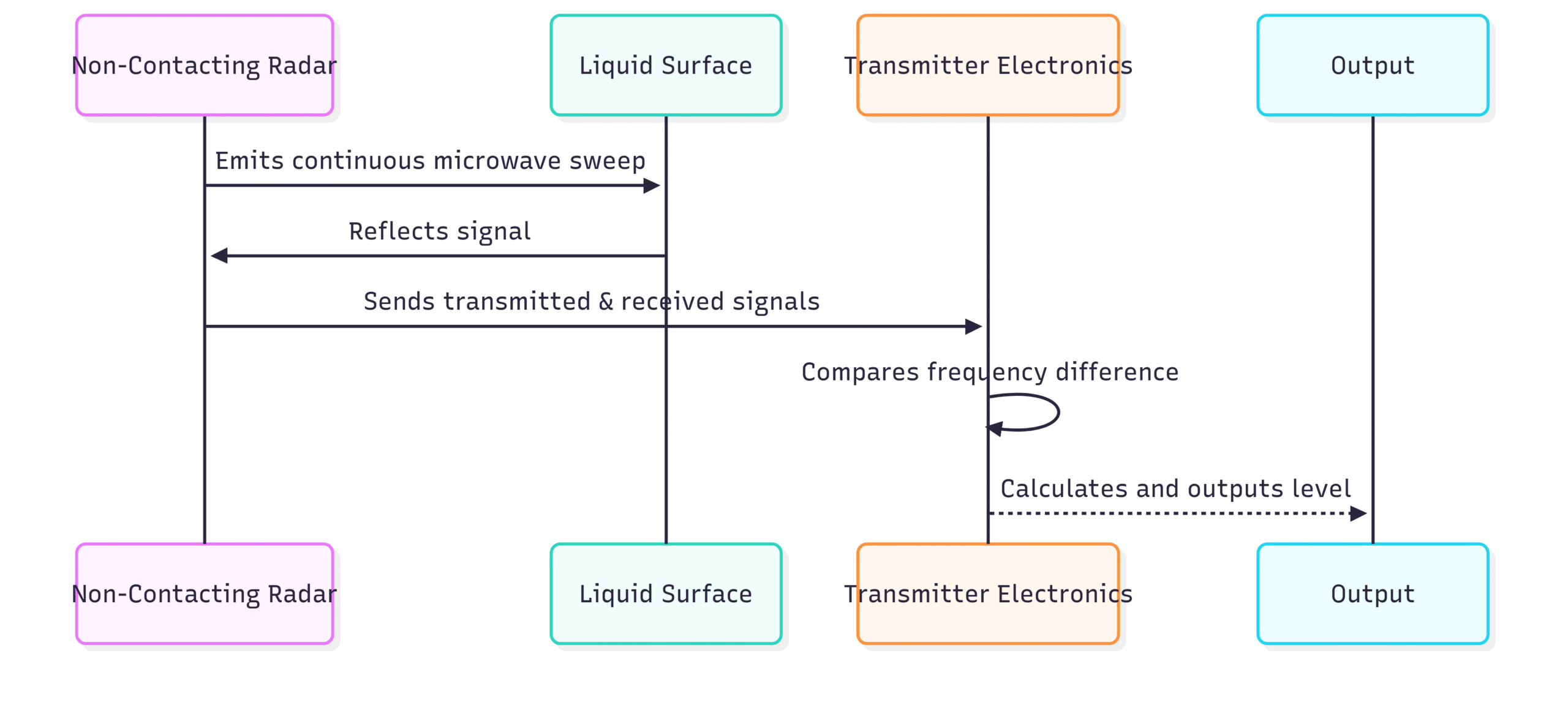
Frequency Modulated Continuous Wave (FMCW) Radar: FMCW transmitters emit a continuous signal that constantly changes its frequency. The transmitter then compares the frequency of the returning signal with the frequency of the signal being emitted at that moment. The difference in frequency is directly proportional to the distance to the surface. FMCW technology generally provides a stronger signal and better signal-to-noise ratio, making it more robust in challenging conditions.
Advantages of NCR in Oil & Gas:
Non-invasive: No direct contact with the process fluid, eliminating concerns about corrosion or contamination.
Low Maintenance: With no moving parts and no contact with the medium, maintenance requirements are minimal.
Ideal for Harsh Chemicals: Perfect for measuring aggressive substances like acids or caustics found in refineries.
Limitations of NCR:
Foam and Turbulence: Heavy foam or extreme turbulence can absorb or scatter the microwave signal, potentially affecting accuracy.
Low Dielectric Media: Liquids with very low dielectric constants (like some light hydrocarbons) reflect a weaker signal, which can be challenging for some older pulsed radar systems.
Condensation: Heavy condensation on the antenna can also impact performance.
Guided Wave Radar (GWR) Level Transmitters
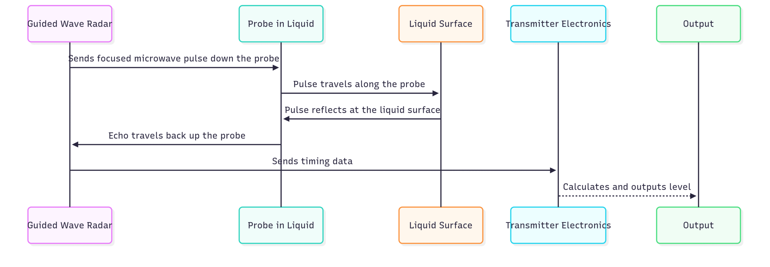
Guided Wave Radar transmitters also operate on the Time of Flight principle, but with a key difference: the microwave pulses are not sent through the open air of the vapor space. Instead, they are guided along a rigid or flexible probe that extends from the transmitter at the top of the tank down into the process medium.
The probe acts as a waveguide, focusing the microwave energy and ensuring a clean, strong signal return, even in the most difficult process conditions. When the pulse traveling down the probe reaches the surface of the liquid, a significant portion of the energy is reflected back up the probe to the transmitter’s electronics.
Advantages of GWR in Oil & Gas:
Superior Performance in Challenging Conditions: GWR is largely unaffected by foam, vapor, turbulence, or changes in pressure and temperature.
Excellent for Low Dielectric Media: The focused signal along the probe ensures a strong return even from materials with very low dielectric constants, such as LPG, propane, and butane.
Interface Level Measurement: A key advantage of GWR is its ability to measure the interface between two immiscible liquids, such as oil and water in a separator. The pulse will reflect a portion of its energy from the upper liquid’s surface (the oil) and another portion from the lower, higher-dielectric liquid’s surface (the water).
Limitations of GWR:
Invasive: The probe is in direct contact with the process medium, which can be a concern with highly corrosive or sticky substances that could cause buildup.
Limited in Tanks with Agitators: The probe can be an obstruction in tanks with large mixers or agitators.
Mechanical Constraints: The length of the probe is limited by the height of the tank, and in very deep tanks, a flexible cable probe is required.
Why Radar Technology Excels in Oil and Gas Applications
The oil and gas industry is notorious for its challenging process environments. Radar level transmitters, in both their non-contacting and guided wave forms, are uniquely suited to overcome these challenges.
Challenge 1: Extreme Temperatures and Pressures
From cryogenic LNG storage tanks to high-pressure steam drums, oil and gas processes span a vast range of temperatures and pressures. Radar transmitters are constructed with robust materials and can be isolated from the process using high-temperature and high-pressure seals, ensuring reliable operation without being affected by these extreme conditions.
Challenge 2: Corrosive and Abrasive Materials
Crude oil often contains sulfur compounds and other corrosive elements. Non-contacting radar, with no part of the instrument touching the fluid, is inherently immune to corrosion and abrasion. For guided wave radar applications, probes can be constructed from highly resistant materials like Hastelloy or can be coated with PFA to withstand aggressive media.
Challenge 3: Low Dielectric Constants
Many hydrocarbons, such as gasoline, diesel, and LPG, have very low dielectric constants, meaning they are poor reflectors of microwave energy. This is where modern radar technology truly shines. The high-frequency signals of 80 GHz non-contacting radars and the focused energy of guided wave radars provide the necessary signal strength to get a clear and stable reading from these difficult-to-measure products.
Challenge 4: Foam, Vapor, and Turbulence
In separators and agitated tanks, foam and turbulence are common occurrences. Guided wave radar is the champion in these scenarios, as the signal is guided directly to the liquid’s surface, bypassing any foam layers. Advanced signal processing algorithms in modern non-contacting radars also allow them to filter out the “noise” from turbulence and provide a stable level reading.
Challenge 5: Interface Level Measurement
In many upstream and downstream processes, separating oil from water is a critical step. Guided wave radar is the ideal technology for this application. It can simultaneously measure both the overall level (the top of the oil) and the interface level (where the oil and water meet), providing crucial data for controlling the separation process efficiently.
Real-World Applications of Radar in Oil and Gas
The versatility of radar level transmitters means they can be found in virtually every segment of the industry.
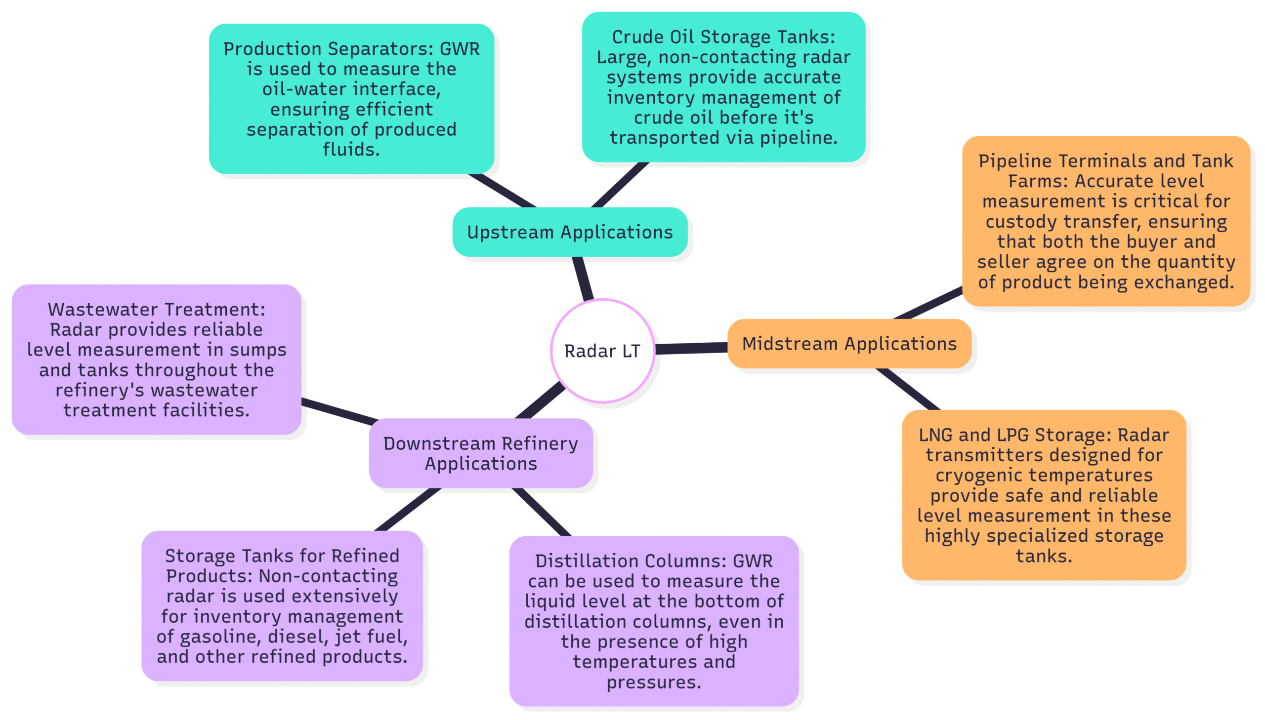
Upstream Applications
Production Separators: GWR is used to measure the oil-water interface, ensuring efficient separation of produced fluids.
Crude Oil Storage Tanks: Large, non-contacting radar systems provide accurate inventory management of crude oil before it’s transported via pipeline.
Midstream Applications
Pipeline Terminals and Tank Farms: Accurate level measurement is critical for custody transfer, ensuring that both the buyer and seller agree on the quantity of product being exchanged.
LNG and LPG Storage: Radar transmitters designed for cryogenic temperatures provide safe and reliable level measurement in these highly specialized storage tanks.
Downstream (Refinery) Applications
Distillation Columns: GWR can be used to measure the liquid level at the bottom of distillation columns, even in the presence of high temperatures and pressures.
Storage Tanks for Refined Products: Non-contacting radar is used extensively for inventory management of gasoline, diesel, jet fuel, and other refined products.
Wastewater Treatment: Radar provides reliable level measurement in sumps and tanks throughout the refinery’s wastewater treatment facilities.
Installation and the Future of Radar Level Measurement
Proper installation is key to unlocking the full potential of a radar level transmitter. This includes selecting the optimal mounting location to avoid interference from tank walls, agitators, or filling streams. However, one of the significant advantages of modern radar transmitters is their ease of setup, often featuring user-friendly software that simplifies commissioning.
The future of radar level technology is already here and continues to advance rapidly:
Higher Frequencies (80 GHz Radar): The use of 80 GHz radar transmitters provides a much more focused beam, which is excellent for avoiding obstructions inside the tank and for getting accurate readings in very tall, narrow silos.
Advanced Diagnostics: Modern transmitters come with powerful diagnostic capabilities (compliant with standards like NAMUR NE 107) that can predict potential issues like probe buildup before they lead to a measurement error.
IIoT and Wireless Connectivity: Integration with the Industrial Internet of Things (IIoT) allows for remote monitoring and configuration of radar level transmitters, providing valuable data for predictive maintenance and process optimization.
The Clear Choice for a Demanding Industry
In conclusion, the journey of the radar level transmitter from a clever application of microwave physics to the go-to instrument for the oil and gas industry is a testament to its inherent robustness, accuracy, and versatility. By operating on the reliable Time of Flight principle and offering both non-contacting and guided wave solutions, radar technology can tackle the full spectrum of challenges presented by the industry—from the corrosive nature of crude oil to the turbulent surfaces in separators and the low dielectric properties of refined hydrocarbons.
As the industry continues to push the boundaries of efficiency and safety, the role of advanced instrumentation like radar level transmitters will only become more critical. They are the unseen sentinels, standing guard over valuable assets, protecting the environment, and ensuring the smooth, safe, and profitable operation of the global oil and gas enterprise.