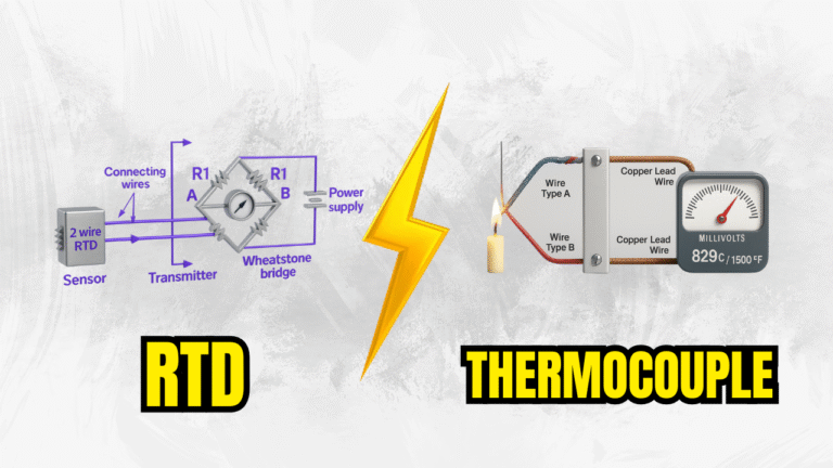
Thermocouple vs. RTD
An Interactive Guide to Choosing the Right Temperature Sensor
Which Sensor is Right for You?
Start here by selecting your most important requirement. We'll highlight the best choice for your scenario throughout this guide.
Performance Dashboard
Visually compare the key performance metrics of each sensor type.
At-a-Glance Comparison
A detailed breakdown of the primary differences between RTDs and Thermocouples.
RTD (Resistance Temperature Detector)
- Principle: Resistance changes predictably with temperature.
- Temperature Range: Narrower (-200°C to 850°C).
- Accuracy: Very High (typically ±0.1°C). Excellent for precision tasks.
- Stability: Excellent long-term stability and repeatability with minimal drift.
- Linearity: Highly linear output.
- Response Time: Slower (1-5 seconds).
- Cost: Higher initial cost.
- Durability: More fragile, sensitive to vibration.
Thermocouple
- Principle: Voltage generated by two dissimilar metals (Seebeck effect).
- Temperature Range: Much Wider (-270°C to 2300°C).
- Accuracy: Lower (typically ±1.0°C). Good for general purpose.
- Stability: Good, but can drift over time due to chemical changes.
- Linearity: Non-linear output ('S' curve).
- Response Time: Faster (< 1 second for exposed tips).
- Cost: Lower initial cost.
- Durability: Very rugged and resistant to vibration.
How They Work
A simplified look at the physics behind each sensor.
RTD: Changing Resistance
Current In →
Resistive Element (Platinum)
As temperature increases,
resistance to current flow increases.
Thermocouple: Generating Voltage
Heating the junction of two different metals creates a small measurable voltage.
Common Applications
Where you'll typically find each type of sensor in the real world.
RTD Applications
- Laboratory and scientific research
- Pharmaceutical manufacturing
- Food and beverage processing
- HVAC systems and climate control
- Precision instrumentation
- Aerospace sensors
Thermocouple Applications
- Industrial furnaces and ovens
- Automotive engines and exhausts
- Energy and power generation
- Metal and steel processing
- Plastics and rubber manufacturing
- Cryogenic storage
Comprehensive Research Report
Introduction to Temperature Measurement
Temperature is one of the most measured physical parameters in science and industry. Accurate temperature measurement is critical for process control, safety, and quality assurance across countless applications. Two of the most common and versatile electronic temperature sensors used today are Resistance Temperature Detectors (RTDs) and Thermocouples. While both serve the same fundamental purpose, they operate on entirely different physical principles and offer distinct advantages and disadvantages, making the choice between them highly dependent on the specific application requirements.
Thermocouples: In-Depth Analysis
Core Principle: The Seebeck Effect
A thermocouple operates based on the Seebeck effect, a thermoelectric phenomenon. This effect states that when two wires made of different metals are joined at one end (the measuring junction), a voltage is produced that is proportional to the temperature at that junction. This voltage arises because the temperature change causes electrons to move differently in the two metals, creating an electromotive force (EMF). To measure this, a voltmeter is connected to the other ends of the wires (the reference junction). The measured voltage directly correlates to the temperature difference between the measuring junction and the reference junction.
Construction and Types
Thermocouples are constructed from various combinations of metal alloys. The specific pairing of metals determines the thermocouple's "type" and its corresponding measurement range, sensitivity, and chemical resistance. They are broadly categorized into base metal and noble metal types.
- Base Metal Thermocouples (Types K, J, T, E, N): These are the most common due to their lower cost and robust performance.
- Type K (Chromel-Alumel): The most popular general-purpose thermocouple with a wide range (-200°C to 1260°C).
- Type J (Iron-Constantan): Offers higher sensitivity in a more restricted range (-40°C to 760°C). Not suitable for oxidizing atmospheres above 540°C.
- Type T (Copper-Constantan): Very stable and ideal for low-temperature and cryogenic applications (-200°C to 370°C).
- Noble Metal Thermocouples (Types R, S, B): Made from platinum and rhodium alloys, these are used for high-temperature applications where high accuracy and stability are required. They are significantly more expensive.
- Type S (Platinum-10% Rhodium): Used as a standard for calibrating other thermocouples up to 1480°C.
Key Operational Considerations
Cold Junction Compensation (CJC): Since a thermocouple measures a temperature *difference*, the temperature at the reference junction must be known to calculate the absolute temperature at the measuring junction. Modern instruments achieve this with "cold junction compensation," where a separate temperature sensor (like a thermistor) measures the ambient temperature at the instrument's terminals and algorithmically compensates for it, ensuring an accurate absolute temperature reading.
Drift and Stability: Over time, especially at high temperatures, the metallurgical properties of the thermocouple wires can change due to oxidation, corrosion, or contamination. This alters the voltage output for a given temperature, a phenomenon known as "drift." This drift is irreversible and necessitates periodic recalibration or replacement for applications requiring long-term stability.
Point Measurement: A unique advantage is that the measurement occurs at the precise point where the two wires are welded together. This allows for very localized temperature readings, which is beneficial in applications where temperature gradients exist.
Resistance Temperature Detectors (RTDs): In-Depth Analysis
Core Principle: Temperature-Dependent Resistance
An RTD functions on the principle that the electrical resistance of a pure metal increases in a highly predictable and repeatable manner as its temperature increases. An RTD is a passive sensor, meaning it does not produce its own output. To measure temperature, a measurement instrument passes a small, constant electrical current through the sensor element. The instrument then measures the resulting voltage drop across the element. Using Ohm's Law (R = V/I), the resistance of the sensor is precisely calculated. This resistance value is then converted into a temperature reading using internationally standardized calibration curves (like the DIN/IEC 60751 standard for platinum RTDs).
Construction and Materials
The overwhelming material of choice for RTDs is platinum because of its exceptional chemical inertness, stability, and nearly linear resistance-temperature relationship. The "Pt100" is the industry standard, signifying a platinum RTD with a resistance of 100 ohms at 0°C. RTD elements are typically constructed in two main forms:
- Wire-Wound: A fine platinum wire is coiled and carefully secured within a ceramic or glass core. This strain-free design allows for the highest accuracy and stability but makes the sensor more susceptible to mechanical shock.
- Thin-Film: A thin layer of platinum is deposited onto a ceramic substrate, and the resistive path is etched into it. Thin-film RTDs are more resistant to vibration and are generally less expensive, but they are often less accurate than their wire-wound counterparts at very high temperatures.
Wiring Configurations
The resistance of the lead wires connecting the RTD element to the instrument can introduce significant measurement errors. To combat this, different wiring configurations are used:
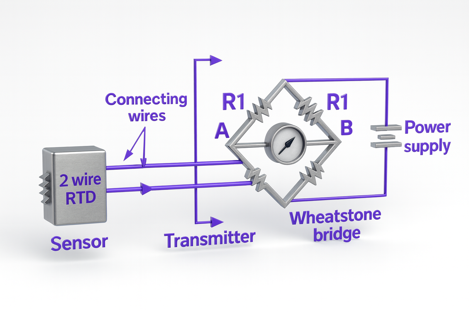
- 2-Wire: The simplest and least accurate configuration. The resistance of the lead wires is added to the sensor's resistance, making it suitable only for short distances where high accuracy is not required.
- 3-Wire: The most common configuration in industrial applications. It uses a third wire to measure the resistance of one of the leads, assuming all leads have equal resistance. This allows the instrument to subtract the lead wire resistance from the total measurement, significantly improving accuracy.
- 4-Wire: The most accurate configuration. Two wires supply the excitation current, and the other two wires measure the voltage drop directly at the RTD element. Since virtually no current flows through the voltage-measuring leads, their resistance has no effect on the reading. This method completely eliminates lead wire error and is used for laboratory and high-precision applications.
Key Operational Considerations
Self-Heating: The small current used to measure the RTD's resistance generates a tiny amount of heat in the sensing element. This can cause the RTD to report a slightly higher temperature than the actual ambient temperature, creating a small error. This effect is usually negligible but must be considered in high-precision measurements.