When it comes to industrial and scientific temperature measurement, two titans dominate the field: the Resistance Temperature Detector (RTD) and the thermocouple. Both are reliable and accurate, but their underlying principles and, crucially, their installation requirements differ significantly. Choosing the right sensor is only half the battle; installing it correctly is paramount to achieving accurate and dependable readings. An improper installation can lead to measurement errors, process inefficiencies, and even safety hazards.
This comprehensive guide dives deep into the world of RTD vs. Thermocouple installation. We’ll explore the nuances of wiring each sensor, highlight the critical differences, and provide practical, step-by-step insights to ensure you get it right the first time. From understanding lead wire resistance in RTDs to mastering cold junction compensation in thermocouples, this article is your ultimate resource for flawless temperature sensor installation.
Understanding the Core Differences: RTD vs. Thermocouple
Before we dig into the nuts and bolts of installation, let’s have a quick refresher on how these sensors work. Their operating principles are the foundation of their installation requirements.
Resistance Temperature Detector (RTD): An RTD operates on the principle that the electrical resistance of a metal changes predictably with temperature. As the temperature increases, the resistance of the metal (typically platinum, hence Pt100 or Pt1000) also increases. The measuring instrument passes a small, known current through the RTD element and measures the resulting voltage drop to calculate the resistance and, subsequently, the temperature. The key takeaway here is that an RTD is a resistive device. This fact is central to its installation.
Thermocouple: A thermocouple works based on the Seebeck effect. It consists of two wires made from different metals joined at one end, the “hot junction” or measuring junction. When this junction is heated or cooled, a small voltage (millivolts) is produced, which is proportional to the temperature difference between the measuring junction and the other end, the “cold junction.” A thermocouple is a voltage-generating device. This is the most critical aspect of its installation.
The fundamental difference—resistance measurement vs. voltage generation—dictates everything from the type of wire used to the configuration and the considerations for avoiding signal interference.
Installing RTDs: Precision and Lead Wire Compensation
Installing an RTD correctly is all about mitigating the impact of lead wire resistance. Since the RTD itself is a resistor, the resistance of the copper wires connecting it to the measuring device can add to the total resistance, creating a positive measurement error (making the reading higher than the actual temperature). To combat this, RTDs come in three main wiring configurations: 2-wire, 3-wire, and 4-wire.
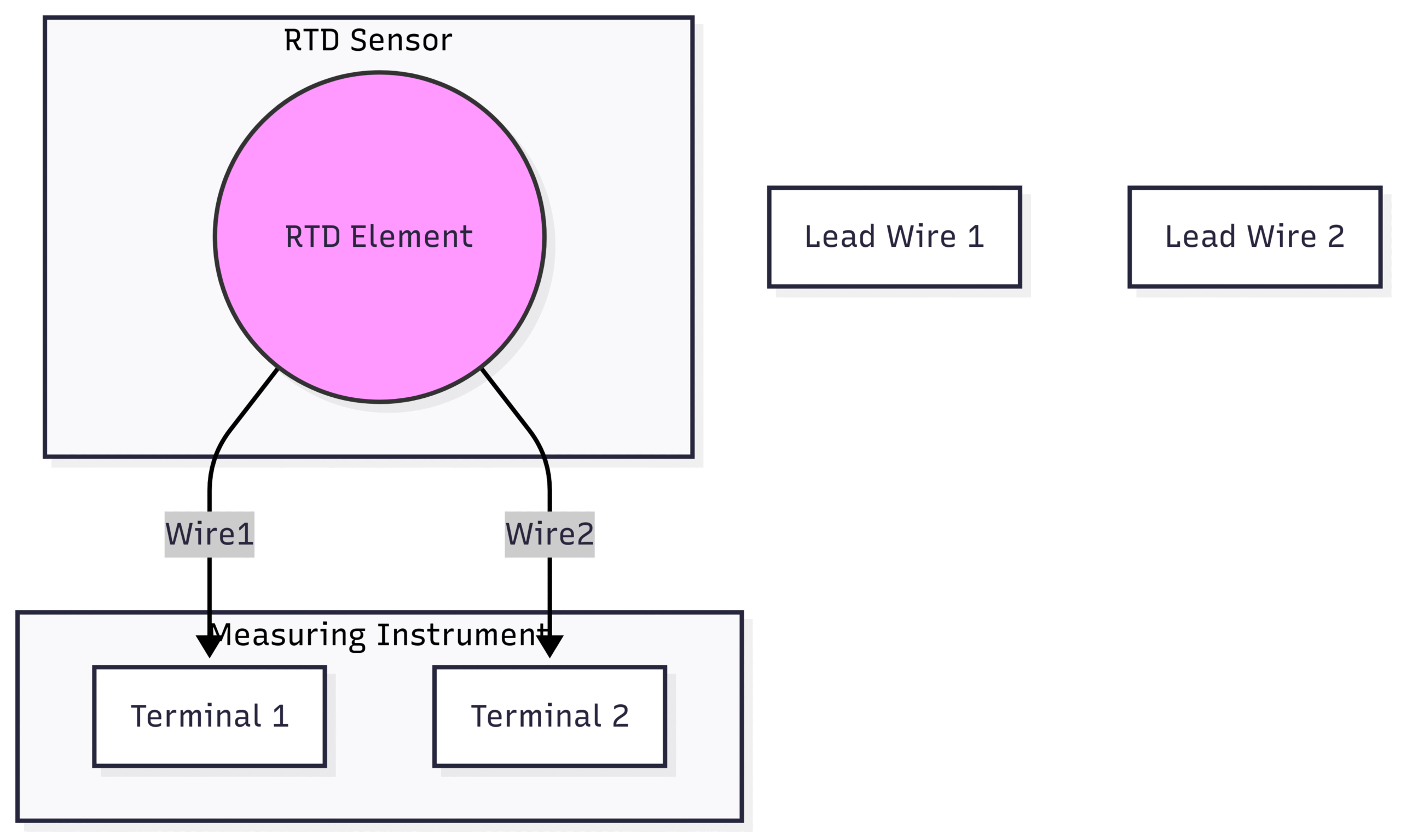
2-Wire RTD Installation
The 2-wire configuration is the simplest but least accurate. It’s generally only suitable for short wire runs (a few feet) and applications where high precision is not required.
How it Works: Two wires connect the RTD element to the transmitter or controller. The instrument measures the total resistance of the circuit, which includes the RTD element and the two lead wires.
The Problem: The system cannot differentiate between the resistance of the sensor and the resistance of the wires. As the wire length increases, so does the added resistance, leading to significant inaccuracies.
Installation Steps:
Connect the two lead wires from the RTD sensor directly to the corresponding input terminals on the measuring device.
Ensure connections are tight and secure to prevent intermittent contact, which can cause erratic readings.
Use shielded cable in electrically noisy environments to protect the low-level resistance signal.
2-Wire RTD Installation
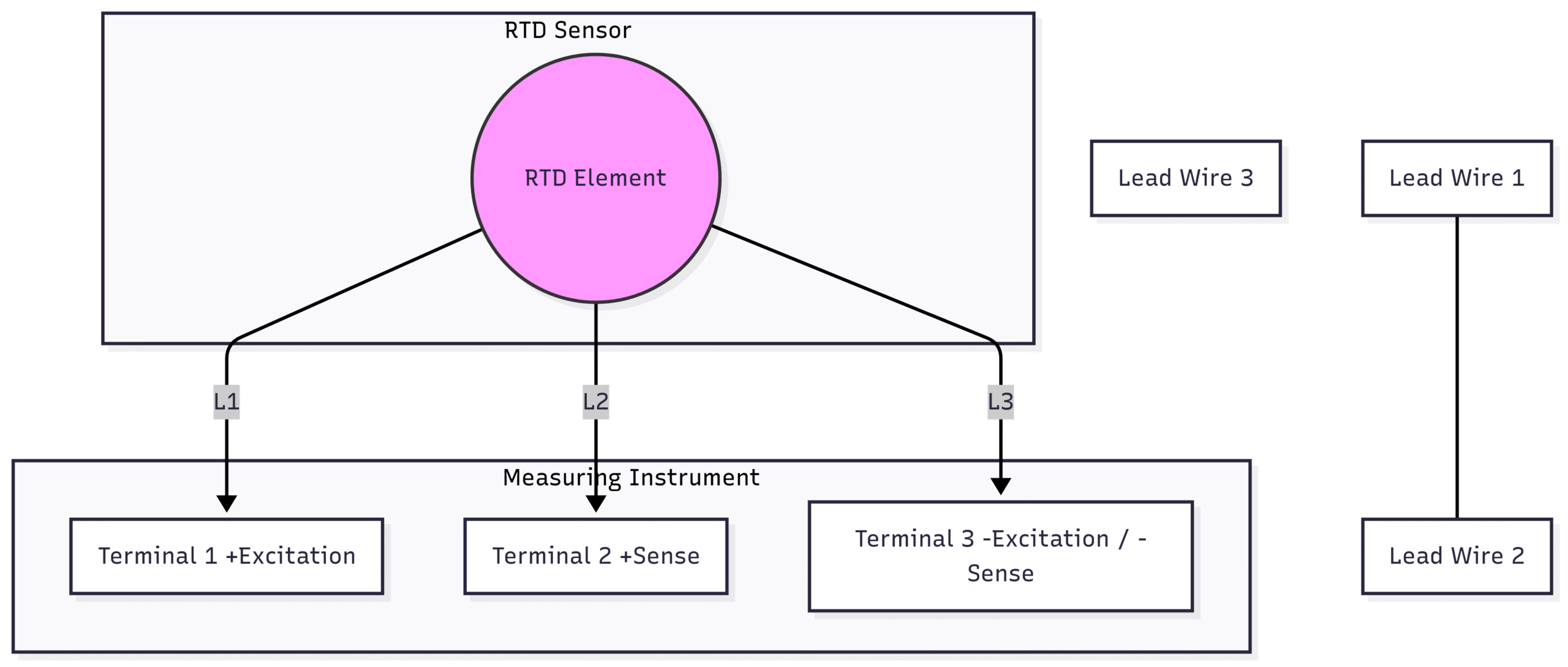
3-Wire RTD Installation
This is the most common configuration in industrial applications. It offers a smart and cost-effective compromise, providing good accuracy by compensating for lead wire resistance.
How it Works: Three lead wires are used. Two wires connect to one side of the RTD element, and one wire connects to the other. The controller sends a current down one wire, through the element, and back through the second wire. The third wire is connected to one side of the RTD and acts as a voltage sense lead. By measuring the resistance of the loop formed by two of the wires (assuming all three wires are the same length and material), the controller can calculate the resistance of a single lead wire and subtract it from the total measurement.
The Advantage: It effectively removes the resistance of the lead wires from the final calculation, leading to much higher accuracy than a 2-wire setup.
Installation Steps:
Identify the two common wires (usually the same color) and the single unique wire from the RTD probe. The two common wires are connected to the same side of the RTD element.
Connect the two common wires to the appropriate terminals on the instrument (often labeled ‘Excitation+’ and ‘Sense-‘).
Connect the third, unique wire to its corresponding terminal (often ‘Sense+’).
Crucially, all three wires must be of the same gauge and length for the compensation to work correctly. Using extension cables of a different type or gauge will introduce errors.
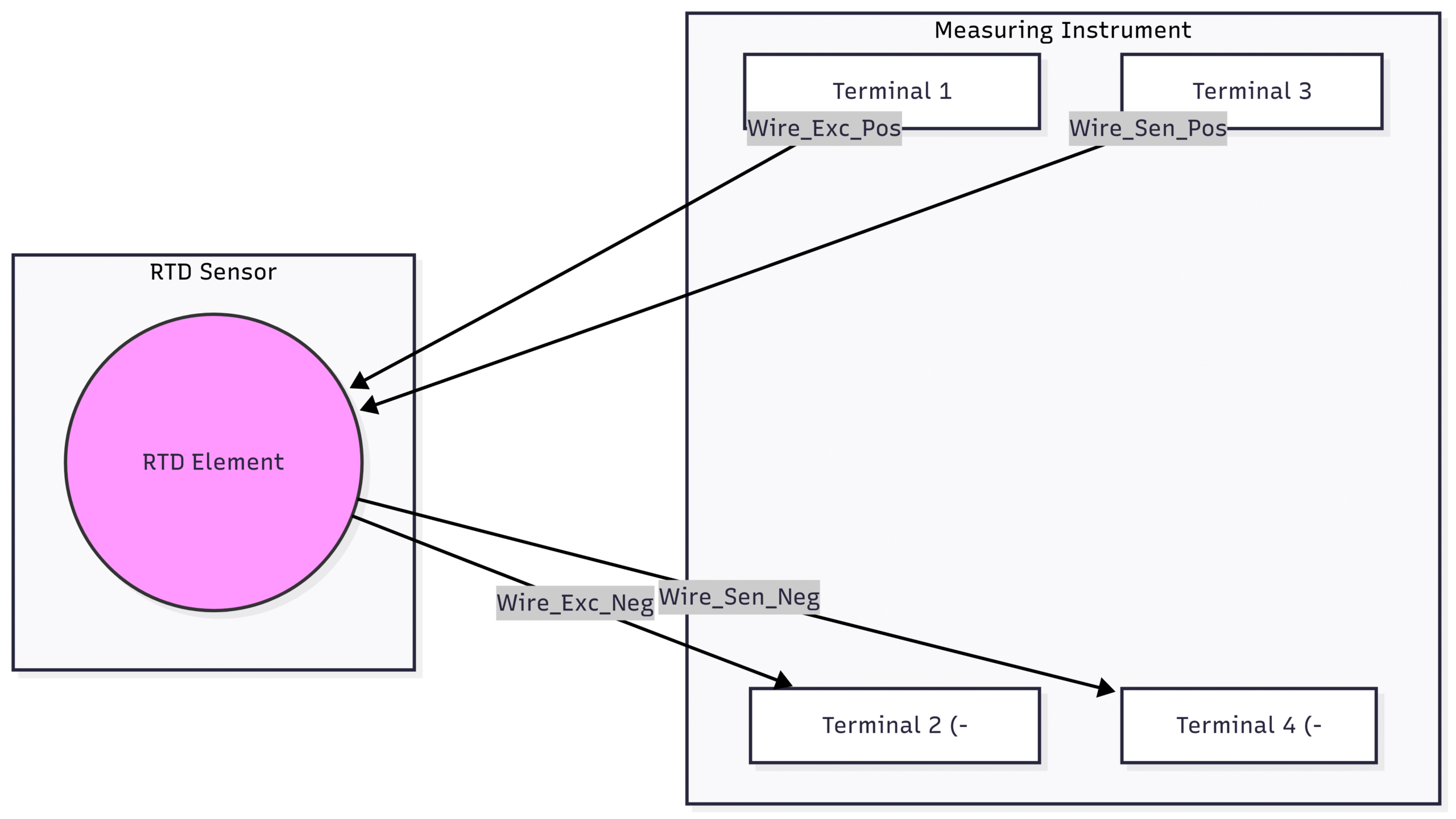
4-Wire RTD Installation
The 4-wire configuration provides the highest possible accuracy and is the standard for laboratory and calibration work. It completely eliminates the effects of lead wire resistance and any variations between them.
How it Works: Two wires provide a constant excitation current to the RTD element, while the other two wires measure the voltage drop directly across the element. Because the voltage-measuring circuit has a very high impedance, virtually no current flows through the voltage sense leads. Therefore, their resistance has no effect on the measurement.
The Advantage: It offers true, uncompromised measurement of the sensor’s resistance, regardless of lead wire length or resistance imbalances.
Installation Steps:
Connect the two excitation wires (often red) from the RTD to the ‘Excitation+’ and ‘Excitation-‘ terminals on the instrument.
Connect the two sense wires (often white or blue) to the ‘Sense+’ and ‘Sense-‘ terminals.
The order of connection is critical. Mixing up excitation and sense leads will result in incorrect readings. Always consult the instrument’s manual.
Mermaid Diagram: 4-Wire RTD Installation
Installing Thermocouples: Managing Voltage and the Cold Junction
Thermocouple installation presents a different set of challenges. Instead of worrying about lead wire resistance, the focus is on preserving the tiny millivolt signal and correctly managing the temperature at the cold junction.
The Importance of Thermocouple Extension Wire
You cannot simply extend a thermocouple’s wires with standard copper cable. Doing so would create a new, unwanted thermocouple junction where the special thermocouple metals meet the copper wire. This would introduce a temperature measurement error at that connection point.
What to Use: You must use the correct thermocouple extension wire or grade wire. This wire is made of the same alloys (or alloys with a very similar thermoelectric profile) as the thermocouple itself.
Color Coding: Thermocouple wires are color-coded according to international standards (e.g., IEC, ANSI) to ensure the correct type is used. For example, in the ANSI standard, a Type K thermocouple has a yellow positive lead (Chromel) and a red negative lead (Alumel). The outer jacket of the extension grade wire is typically brown. The red wire is always the negative lead in the US/ANSI standard. This is a common point of confusion.
Polarity: Connecting the wires with the wrong polarity will result in the temperature reading decreasing as the actual temperature increases. Always double-check polarity
Cold Junction Compensation (CJC)
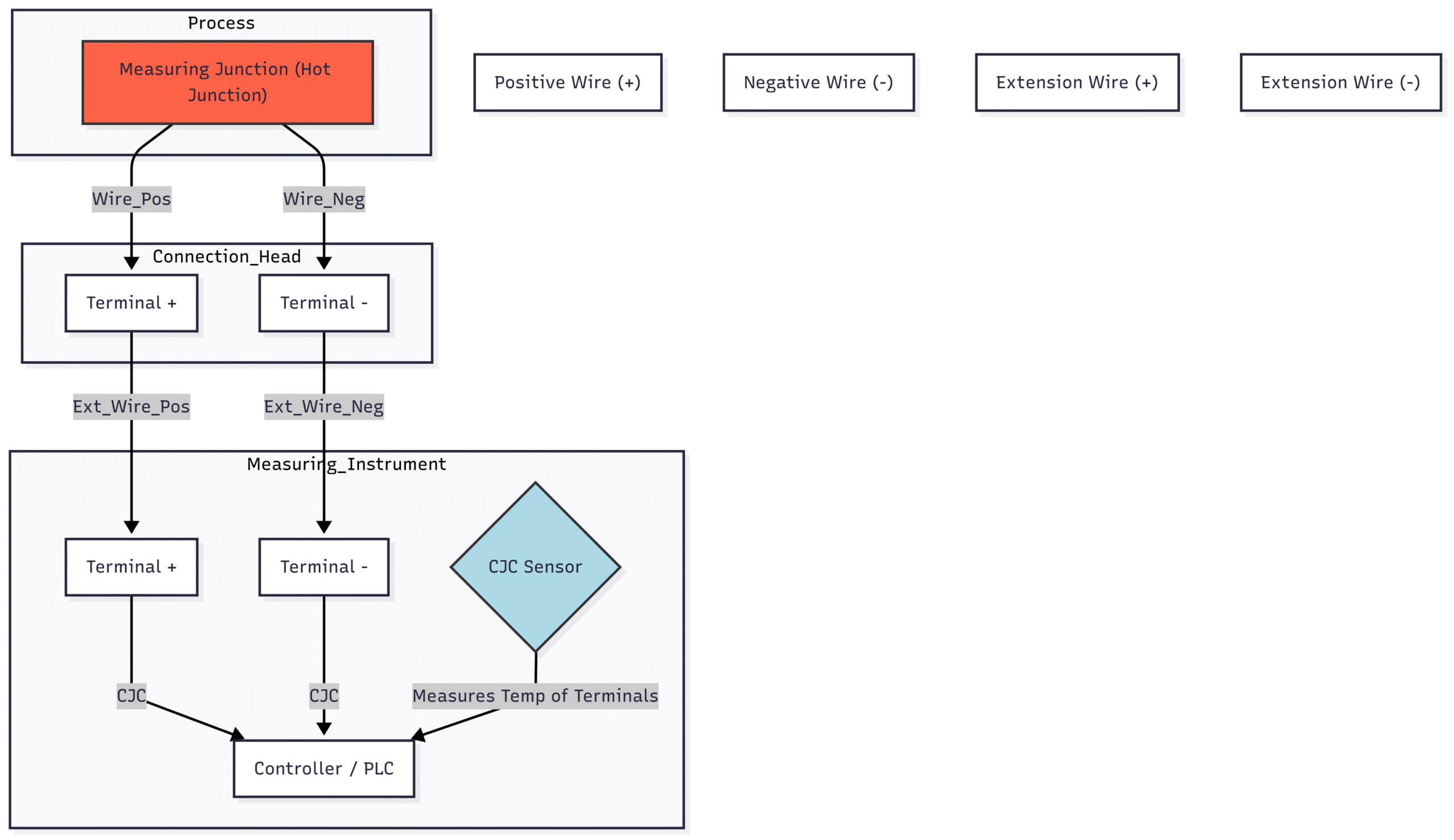
A thermocouple measures the temperature difference between its hot junction (the sensor tip) and its cold junction (where the thermocouple wires connect to the measuring instrument). To get an absolute temperature reading, the instrument must know the temperature of the cold junction and add it to the measured difference. This process is called Cold Junction Compensation (CJC).
How it Works: Modern digital controllers and transmitters have a built-in temperature sensor (often a thermistor or semiconductor sensor) located right at the input terminals. This sensor measures the ambient temperature of the terminal block. The instrument’s software then automatically adds this cold junction temperature to the value derived from the thermocouple’s millivolt output.
Installation Implications:
Stable Environment: Ensure the measuring instrument (and thus the cold junction) is located in an area with a stable ambient temperature. Avoid placing it near heat sources, in direct sunlight, or in cold drafts. Rapid fluctuations in the cold junction temperature will cause unstable readings.
Isothermal Block: The connection terminals on the instrument are designed as an “isothermal block,” meaning they are engineered to keep all terminals at the exact same temperature. Ensure connections are clean and tight to maintain this thermal equilibrium.
General Thermocouple Installation Steps
Select the Right Type: Choose a thermocouple type (K, J, T, E, etc.) appropriate for your temperature range and chemical environment.
Mount the Sensor: Position the measuring junction so it makes good thermal contact with the object or medium you want to measure.
Run the Extension Wire: Route the correct type of extension wire from the sensor head to the measuring instrument. Avoid running it parallel to high-voltage power cables to prevent electromagnetic interference (EMI). If you must cross power lines, do so at a 90-degree angle. Use shielded, twisted-pair extension wire for added noise immunity.
Check Polarity: Carefully connect the positive (+) and negative (-) leads to the correct terminals on the instrument. Remember, for ANSI standards, red is negative.
Verify CJC: Ensure that the cold junction compensation feature is enabled in your instrument’s configuration settings.
Mermaid Diagram: Thermocouple Installation Circuit
Head-to-Head Installation Comparison: RTD vs. Thermocouple
Common Installation Pitfalls and How to Avoid Them
Even experienced technicians can fall into common traps. Here’s what to watch out for:
Using Copper Wire for Thermocouples:
The Pitfall: Extending a thermocouple with regular copper wire.
The Result: Creates an unwanted measurement junction, leading to large, unpredictable errors.
The Fix: ALWAYS use the correct type of thermocouple extension wire. Match the wire type to the sensor type (e.g., Type K wire for a Type K sensor).
Ignoring Lead Resistance in 2-Wire RTDs:
The Pitfall: Using a 2-wire RTD for a precision application with a long wire run.
The Result: The instrument reads the resistance of the wire plus the sensor, causing a falsely high temperature reading.
The Fix: Use a 3-wire or 4-wire RTD for any application that requires accuracy, especially with cable runs over a few meters.
Mismatched Wires in 3-Wire RTDs:
The Pitfall: Extending a 3-wire RTD with cable that has a different gauge or using wires of unequal length.
The Result: The resistance compensation logic fails because it assumes all three wires have identical resistance. This reintroduces measurement error.
The Fix: Use a 3-conductor cable where all conductors are identical. If extending, use the same type of cable.
Reversing Thermocouple Polarity:
The Pitfall: Connecting the positive lead to the negative terminal and vice-versa.
The Result: The reading will go down as the temperature goes up. At room temperature, the error might not be obvious.
The Fix: Pay close attention to wire colors and terminal markings. Remember: Red is Negative in the ANSI standard.
Poor Cold Junction Environment:
The Pitfall: Locating the controller/transmitter where the ambient temperature fluctuates wildly (e.g., next to a furnace door, in a draft).
The Result: The CJC will be inaccurate, causing the final temperature reading to drift and be unstable.
The Fix: Install the instrument in a control cabinet or location with a stable thermal environment.
Ground Loops and EMI:
The Pitfall: Improper grounding or running low-level sensor cables parallel to power cables.
The Result: Electrical noise is induced into the sensor signal, causing erratic or offset readings.
The Fix: Use shielded, twisted-pair cable. Ground the shield at one end only (typically the instrument end) to prevent ground loops. Cross power cables at 90-degree angles.
Conclusion: Choose Wisely, Install Meticulously
The RTD vs. Thermocouple installation debate doesn’t have a single winner. The best choice depends on your application’s requirements for accuracy, temperature range, and cost. However, the success of either choice hinges entirely on a correct and careful installation.
For RTDs, the key is to mitigate the effects of lead wire resistance. For any application demanding precision, a 3-wire or 4-wire configuration is not just recommended; it’s essential.
For thermocouples, the focus is on preserving the integrity of the millivolt signal. This means using the proper extension wire, ensuring correct polarity, and providing a stable environment for the Cold Junction Compensation.
By understanding the fundamental principles of each sensor and following the installation best practices outlined in this guide, you can ensure your temperature measurements are accurate, reliable, and effective. A few extra minutes spent verifying wiring and following the rules will save hours of troubleshooting and prevent costly process errors down the line.