In industrial environments where process control and equipment safety are paramount, pressure gauges serve as critical indicators of system health. Whether in oil and gas, chemical processing, pharmaceuticals, power plants, or general manufacturing, selecting the correct pressure gauge ensures reliable readings, minimizes downtime, and extends the life of your instrumentation.
This comprehensive guide explores the selection criteria for pressure gauges based on key parameters such as application type, gauge filling, dial size, material selection, process connection, and mounting design.
1. Understanding the Basics of a Pressure Gauge
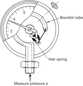
A pressure gauge is an instrument used to measure and display pressure in a system. The most commonly used type is the Bourdon tube pressure gauge, where pressure is converted into mechanical movement. Other types include diaphragm and capsule gauges, used for specific low-pressure or corrosive service conditions.
Key Parameters Displayed:
Gauge pressure (relative to atmospheric pressure)
Absolute pressure (relative to a vacuum)
Differential pressure (difference between two points)
Before diving into selection criteria, it’s essential to define the process conditions:
Medium (gas, liquid, or vapor)
Pressure range
Temperature
Environmental exposure
Presence of vibrations or pulsations
Hazardous area classification
2. Liquid Filling: Dry vs. Liquid-Filled Gauges
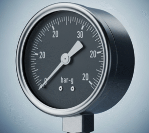
Dry Pressure Gauges:
Best For: General-purpose indoor applications with minimal vibration and pulsation.
Advantages: Cost-effective, simple, suitable for non-corrosive and stable pressure systems.
Disadvantages: Can fog up due to internal moisture condensation; less suitable for harsh environments.
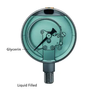
Liquid-Filled Gauges:
Best For: Outdoor, vibrating, pulsating, and corrosive environments (e.g., pumps, compressors, hydraulic circuits).
Common Fill Liquids: Glycerin, silicone oil, mineral oil.
Advantages:
Dampens needle vibrations for easier reading
Reduces wear and tear on internal parts
Extends gauge life in high-cycle or pulsating systems
Helps with visibility by preventing fogging
Selection Based on Application:
| Application | Recommended Gauge Type | Fill Fluid |
|---|---|---|
| Hydraulic systems | Liquid-filled | Glycerin |
| High temperature (>60°C) | Liquid-filled | Silicone oil |
| Food & pharma | Liquid-filled with diaphragm | Non-toxic oil |
| Low vibration, indoor environments | Dry type | Not applicable |
3. Dial Size Selection
Dial size affects readability and the physical space required for mounting. Standard sizes range from 40 mm to 250 mm (1.5” to 10”).
Selection Considerations:
Readability: Larger dials offer better readability from a distance.
Mounting Space: Space-constrained locations may require smaller gauges.
Accuracy Class: Larger dials typically offer higher accuracy due to larger scale divisions.
Dial Size Guidelines:
| Dial Size | Typical Application | Mounting Location |
|---|---|---|
| 40–50 mm | Panel mounted, lab instruments | Local/close viewing |
| 63 mm | General-purpose process measurement | Close monitoring |
| 100 mm | Field service (oil & gas, chemical plants) | Remote/local |
| 150 mm | High-precision and remote readings | Remote field viewing |
| 250 mm | Large-scale industries with long-distance view | Tank farms, control towers |
4. Material Selection for Wetted and Non-Wetted Parts
Choosing appropriate materials ensures gauge longevity, accuracy, and safety in corrosive or hazardous environments.
Wetted Parts:
These are parts that come in contact with the process fluid—primarily the Bourdon tube and socket.
| Process Medium | Recommended Wetted Material |
|---|---|
| Air, Water, Oil | Brass |
| Corrosive Chemicals | 316 Stainless Steel or Monel |
| Acids, Chlorides | PTFE lining, Tantalum, Hastelloy |
| Oxygen | Degreased SS, oil-free systems |
| Steam | SS with siphon or pigtail loop |
Case Materials (Non-Wetted):
These are the external parts like the case and window, exposed to the atmosphere.
| Environment | Case Material | Window Material |
|---|---|---|
| General indoor use | Painted steel | Glass |
| Corrosive atmosphere | SS 304/316 | Laminated safety glass |
| Explosion-proof areas | SS with flameproof enclosure | Glass/polycarbonate |
| Vibration-heavy zones | SS with rubber-sealed window | Acrylic |
Note: For hydrogen service, gauges must use monel or special alloy due to hydrogen embrittlement in SS.
5. Pressure Range and Overpressure Protection
Selection Rule:
Set the pressure range to 1.5 to 2 times the system operating pressure for optimal life and performance.
Example: If your system runs at 5 bar, choose a gauge with a 0–10 bar range.
Overpressure Protection:
Gauges should include built-in overpressure protection or be installed with snubbers or limiters if subject to spikes.
| Process Type | Operating Pressure | Recommended Range |
|---|---|---|
| Hydraulic line | 70 bar | 0–100 bar |
| Steam pipeline | 6 bar | 0–10 bar |
| Fuel tank | 0.5 bar | 0–1 bar |
| High-pressure gas | 150 bar | 0–250 bar |
6. Accuracy Class Selection
Accuracy is defined as the permissible deviation from the actual value, expressed as a percentage of full-scale range.
Standard Accuracy Grades (EN 837-1):
| Accuracy Class | Typical Application |
|---|---|
| ±2.5% | General industrial usage (small dial) |
| ±1.6% | Field instruments |
| ±1.0% | Process instruments |
| ±0.6% to ±0.25% | Laboratory and calibration gauges |
Always refer to EN 837, ASME B40.100, or ISA S40 standards for accuracy class definitions.
7. Process Connection and Mounting Design
Process connections must match the system configuration in terms of thread type, size, and orientation.
Connection Orientation:
Bottom Entry (Radial): Common in panel mounting or direct inline process connections.
Back Entry (Axial): Preferred for panel or flush mounting.
Lower Back Entry: Combines visibility and accessibility in vertical installations.
Thread Standards:
| Region/Standard | Common Thread Types |
|---|---|
| ISO / Europe | BSP (G1/2, G1/4) |
| USA | NPT (1/4″, 1/2″) |
| Custom / OEM | Metric threads |
Mounting Types:
Stem Mount (Bottom): Threaded into process pipe directly.
Surface Mount (Back): Panel-mounted using a back flange.
U-Clamp Mount: For instrument panels.
Flush Panel Mount: Industrial control rooms or cleanrooms.
8. Special Applications and Custom Features
Diaphragm Seals:
Used when process fluid is:
Highly viscous
Crystallizing
Hot or corrosive
Contains solids
Remote diaphragm seals can isolate the gauge from the process, transmitting pressure via capillary and fill fluid.
Snubbers and Pulsation Dampeners:
Recommended for:
Reciprocating pumps
Compressors
Systems with water hammer or pressure surges
These devices reduce mechanical wear and improve reading stability.
Pressure Gauge with Electric Contacts:
Used to initiate alarms or control actions when the pressure reaches set points (e.g., compressor cut-off). Comes in:
Magnetic Snap Action
Inductive Contact
Reed Contact
9. Gauge Selection Checklist
Before finalizing your pressure gauge, run through this essential checklist:
| Parameter | Selection Example |
|---|---|
| Pressure range | 0–10 bar (if operating at 5 bar) |
| Gauge type | Liquid-filled Bourdon tube |
| Accuracy class | ±1.0% for process, ±0.25% for lab |
| Dial size | 100 mm for field, 150 mm for remote |
| Wetted material | SS 316 for chemicals |
| Case material | SS 304 for outdoor exposure |
| Process connection | 1/2” NPT Male, bottom entry |
| Mounting | Stem mount or surface mount |
| Accessories | Snubber, diaphragm seal if needed |
| Compliance | EN 837, ASME B40.100 |
10. Summary and Best Practices
Selecting the right pressure gauge is not just about pressure range—it’s about choosing the optimal configuration for accuracy, durability, safety, and readability in the context of your application.
Best Practices:
Always choose a range 1.5–2 times the operating pressure.
Use liquid-filled gauges in vibration or pulsation-prone environments.
Select stainless steel wetted parts for corrosive fluids.
Install siphons for steam service to protect the gauge from high temperature.
Use diaphragm seals for aggressive, high-viscosity, or sanitary media.
Verify conformity with industry standards (EN, ASME, API, etc.)
Conclusion
A pressure gauge may seem like a small component, but its role in system integrity and process control is huge. By understanding the operational demands of your system and the material, mechanical, and design properties of available gauges, you can make informed decisions that enhance safety, accuracy, and equipment life.
Take time to assess your process conditions and consult manufacturer datasheets or instrumentation engineers before making a final selection. The right pressure gauge is not just a measurement tool—it’s a safeguard for your entire operation.