SIL Determination Explained: IEC 61508 vs. IEC 61511 Approach
In the world of industrial automation and process safety, ensuring the reliability of safety systems is not just a matter of good practice; it’s a critical necessity mandated by stringent international standards. Two of the most pivotal standards in this domain are IEC 61508 and IEC 61511. While both address functional safety and the determination of Safety Integrity Levels (SIL), they approach the subject from different perspectives. This blog post will provide a comprehensive 2000-word explanation of SIL determination, dissecting the distinct methodologies of IEC 61508 and IEC 61511, complete with illustrative block diagrams.
The Foundation of Functional Safety: A Tale of Two Standards
Before delving into the intricacies of SIL determination, it’s essential to understand the relationship between these two cornerstone standards.
IEC 61508, titled “Functional Safety of Electrical/Electronic/Programmable Electronic Safety-related Systems,” is the foundational or “umbrella” standard. It provides a generic framework for designing, implementing, and maintaining safety systems across all industry sectors. Its scope is broad, covering everything from the development of a new sensor to the overall safety lifecycle of a complex system. Think of it as the constitution of functional safety.
IEC 61511, on the other hand, is a sector-specific standard derived from IEC 61508. Its full title, “Functional safety – Safety instrumented systems for the process industry sector,” clearly defines its focus. It takes the fundamental principles of IEC 61508 and tailors them to the unique hazards and operational realities of industries like oil and gas, chemicals, pharmaceuticals, and power generation. If IEC 61508 is the constitution, IEC 61511 is the specific legal code for the process industry.
The key takeaway is that compliance with IEC 61511 for a process industry application will, by extension, satisfy the fundamental requirements of IEC 61508. However, IEC 61511 provides more specific, and often more practical, guidance for end-users in this sector.
What is SIL and Why is it Crucial?
A Safety Integrity Level (SIL) is a discrete level (1 to 4) that quantifies the necessary risk reduction provided by a safety function. In simpler terms, it’s a measure of the reliability of a safety system. The higher the SIL, the greater the potential hazard, and therefore, the higher the required level of performance and reliability of the safety function designed to mitigate that hazard.
The determination of the appropriate SIL is arguably the most critical step in the safety lifecycle. An underestimated SIL can lead to inadequate protection and potentially catastrophic consequences. Conversely, an overestimated SIL can result in over-engineered, unnecessarily complex, and expensive safety systems.
The Safety Lifecycle: A Common Framework with Distinct Paths
Both IEC 61508 and IEC 61511 are built around the concept of a safety lifecycle. This is a systematic, phase-by-phase approach that covers the entire life of a safety system, from initial concept to decommissioning. While the overall lifecycle phases are similar, the emphasis and practical application within each phase can differ, particularly concerning SIL determination.
The IEC 61508 Approach: A Generic, Top-Down Perspective
The IEC 61508 standard provides a comprehensive and rigorous framework for SIL determination that is applicable to any industry. Its approach is often seen as more theoretical and centered on the responsibilities of product manufacturers and system developers.
Block Diagram: IEC 61508 Safety Lifecycle and SIL Determination
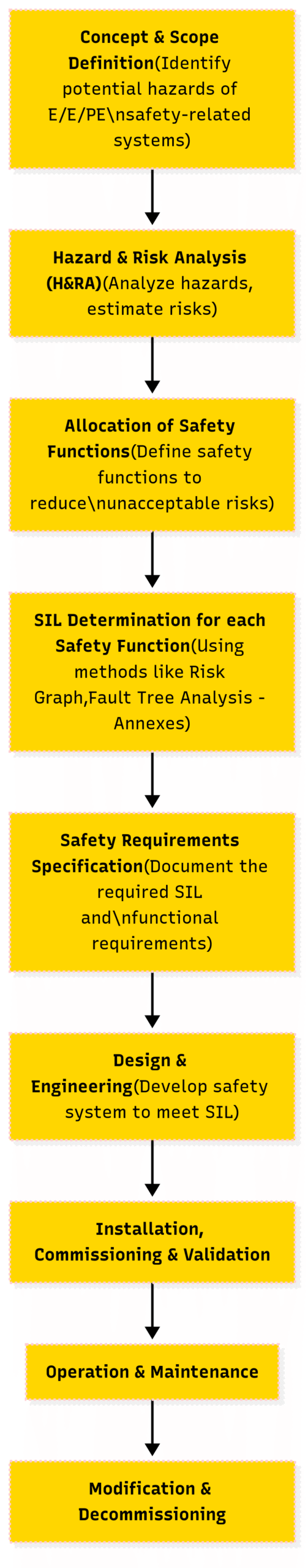
Key Aspects of the IEC 61508 Approach:
Broad Applicability: The methodologies for H&RA and SIL determination in IEC 61508 are intentionally generic to cater to a wide range of applications, from medical devices to nuclear power plants.
Emphasis on Quantitative Analysis: While qualitative methods are permitted, IEC 61508 often encourages a more detailed, quantitative approach to risk assessment, especially for higher SILs. This can involve complex probabilistic calculations.
“Proven in Use” for Component Justification: IEC 61508 introduces the concept of “proven in use” for components that do not have a full, certified design and development process according to the standard. To claim a component is “proven in use,” a manufacturer must provide extensive evidence of its successful and reliable operation in similar applications and environments. This places a significant data collection and analysis burden on the component manufacturer.
The IEC 61511 Approach: A Practical, Process-Industry Focus
IEC 61511 streamlines and adapts the IEC 61508 framework for the process industry. The focus shifts from the theoretical development of safety components to the practical application and management of Safety Instrumented Systems (SIS) within a processing plant.
Block Diagram: IEC 61511 Safety Lifecycle and SIL Determination
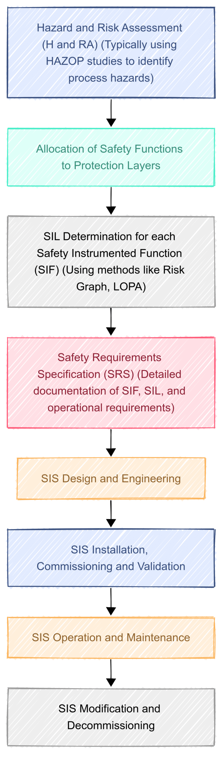
Key Differences in the IEC 61511 Approach:
Process Hazard Analysis (PHA) as the Starting Point: IEC 61511 directly links the safety lifecycle to common process industry practices like Hazard and Operability (HAZOP) studies. The outputs of these PHAs are the direct inputs to the SIL determination process.
Pragmatic SIL Determination Methodologies: IEC 61511 provides more explicit guidance and preference for certain SIL determination methods that are well-suited to the process industry. The two most common are:
Risk Graph: A qualitative or semi-quantitative method that uses a graphical tool to determine the required SIL based on a series of parameters like the consequence of the hazardous event, the frequency of exposure to the hazard, the possibility of avoiding the hazard, and the demand rate on the safety function.
Layers of Protection Analysis (LOPA): A semi-quantitative method that is widely used in the process industry. LOPA systematically analyzes the layers of protection that are in place to prevent a hazardous event and determines if the existing layers are sufficient or if a Safety Instrumented Function (SIF) is required, and at what SIL.
“Prior Use” for Component Justification: This is a crucial distinction from IEC 61508. “Prior use” allows an end-user in the process industry to justify the use of a component that is not fully IEC 61508 certified, based on their own documented operating experience with that component in a similar application and environment. This empowers the end-user, who has the most relevant operational data, to make informed decisions about component selection. The burden of proof shifts from the manufacturer to the user.
A Deeper Dive into SIL Determination Methodologies under IEC 61511
Let’s explore the two most prominent SIL determination methods in the process industry in more detail.
Risk Graph: A Visual Approach to SIL Determination
The Risk Graph method offers a structured and relatively straightforward way to determine the target SIL. It involves a team of experts evaluating a hazardous scenario against a set of predefined parameters.
Example of Risk Graph Parameters:
Consequence (C): What are the consequences of the hazardous event? (e.g., C1: Minor injury, C2: Serious injury, C3: Multiple fatalities, C4: Catastrophic event)
Frequency and Exposure (F): How often are people in the hazardous zone? (e.g., F1: Rare, F2: Frequent)
Possibility of Avoidance (P): Can the hazardous event be avoided? (e.g., P1: Possible, P2: Unlikely)
Demand Rate (W): How often is the safety function likely to be called upon? (e.g., W1: Low demand, W2: Medium demand, W3: High demand)
By tracing a path through the risk graph based on the selected parameters for a specific hazard, the team arrives at a required SIL.
Simplified Risk Graph Example:
Imagine a scenario where a high-pressure reactor could over-pressurize, leading to a rupture.
Consequence (C): Multiple fatalities (C3)
Frequency and Exposure (F): Operators are frequently in the area (F2)
Possibility of Avoidance (P): Escape is unlikely once the event starts (P2)
Demand Rate (W): The condition that could lead to overpressure occurs with medium frequency (W2)
Following the path for C3, F2, P2, and W2 on a calibrated risk graph would likely lead to a requirement for a SIL 3 safety function.
Layers of Protection Analysis (LOPA): A Semi-Quantitative Methodology
LOPA is a more detailed and analytical method that has gained widespread acceptance in the process industry. It builds upon the information from a HAZOP and provides a more structured and auditable trail for SIL determination.
The Core Principle of LOPA: LOPA evaluates the risk of a specific hazardous scenario by comparing the frequency of the initiating event with the acceptable risk frequency. The difference between these two values is the required risk reduction that must be provided by the Independent Protection Layers (IPLs). A Safety Instrumented Function (SIF) is one such IPL.
Steps in a LOPA:
Identify the Hazardous Scenario: This is typically taken from a HAZOP study (e.g., “High pressure in Reactor R-101 leads to vessel rupture”).
Determine the Initiating Event Frequency: How often is the initiating event expected to occur? (e.g., “Failure of the pressure controller leading to runaway reaction once every 10 years”).
Define the Tolerable Risk: What is the maximum acceptable frequency for this hazardous event? (e.g., “The company’s risk criteria state that an event of this severity is tolerable once every 10,000 years”).
Identify Independent Protection Layers (IPLs): What other safeguards are in place? (e.g., a pressure relief valve, an operator alarm). Each IPL must be independent of the initiating event and other IPLs.
Calculate the Risk Reduction of Each IPL: Each IPL is assigned a Probability of Failure on Demand (PFD). For example, a pressure relief valve might have a PFD of 0.1 (meaning it fails once in every 10 demands).
Calculate the Mitigated Event Frequency: Multiply the initiating event frequency by the PFDs of all the IPLs.
Determine the SIL Requirement: If the mitigated event frequency is still higher than the tolerable risk, a SIF is required. The required risk reduction from the SIF determines its SIL.
LOPA Example:
Initiating Event Frequency: 0.1 per year (once every 10 years)
Tolerable Risk Frequency: 0.0001 per year (once every 10,000 years)
Required Risk Reduction Factor (RRF): 0.1 / 0.0001 = 1000
Existing IPL: Pressure Relief Valve with a PFD of 0.1 (RRF of 10)
Risk Gap: The relief valve provides a risk reduction of 10, but a total reduction of 1000 is needed.
Required SIF RRF: 1000 / 10 = 100
Required SIL: A risk reduction factor of 100 corresponds to SIL 2.
Conclusion: Choosing the Right Approach
The choice between the IEC 61508 and IEC 61511 approach to SIL determination is largely dictated by your role and industry.
For component manufacturers and developers of safety systems intended for broad use, a thorough understanding and application of the generic IEC 61508 framework is essential. The focus is on providing a certified, reliable product with comprehensive safety data.
For end-users in the process industry, IEC 61511 provides a more practical and tailored roadmap. It empowers them to leverage their process knowledge and operational data to make informed and justifiable SIL decisions using methods like Risk Graphs and LOPA. The concept of “prior use” is a testament to this user-centric approach.
Ultimately, both standards share the same goal: to ensure that safety systems are designed, implemented, and maintained to a level of integrity that effectively mitigates risks and protects people, the environment, and assets. By understanding the nuances of each standard’s approach to SIL determination, organizations can navigate the complexities of functional safety with greater confidence and achieve a safer and more reliable operation.