
Checklist and Activities: Preparations for an Instrument Engineer Before a SIL Workshop
In the world of process safety, the Safety Integrity Level (SIL) workshop is a cornerstone event. It’s where the critical decisions are made about the safety layers required to protect personnel, the environment, and assets from potential hazards. For an Instrument & Control (I&C) Engineer, this isn’t just another meeting—it’s a high-stakes technical deep dive where your expertise is front and center.
Walking into a SIL workshop unprepared is like trying to navigate a maze blindfolded. You’ll slow down the process, risk incorrect SIL assignments, and potentially compromise the integrity of the plant’s safety systems. Thorough preparation is not just recommended; it’s an absolute necessity. It empowers you to provide accurate data, justify design choices, and contribute meaningfully to the overarching goal of process safety.
This guide provides a comprehensive checklist and a breakdown of activities to ensure you, the Instrument Engineer, are fully prepared to excel in your next SIL workshop.
The Foundation: Why Preparation Matters
The primary goal of a SIL workshop, often conducted as part of a Layer of Protection Analysis (LOPA), is to determine if the existing or proposed safeguards are sufficient to mitigate identified process risks. The workshop team—comprising process engineers, operators, safety specialists, and you—analyzes hazardous scenarios and decides if a Safety Instrumented Function (SIF) is needed. If it is, the team assigns it a target SIL (1, 2, 3, or 4), which dictates its required reliability.
Your role is to provide all the instrumentation-specific information. This includes:
Feasibility: Can a proposed SIF be practically implemented?
Reliability: What are the failure rates of the proposed sensors, logic solvers, and final elements?
Testability: How will the SIF be tested, and how often?
Architecture: What design (e.g., 1oo2, 2oo3) will meet the SIL target?
Without this information at your fingertips, the workshop grinds to a halt. Decisions are delayed, assumptions are made, and the quality of the safety analysis suffers. By preparing, you transform from a passive attendee into an active, value-adding participant.
Here’s a visual overview of the preparation workflow:
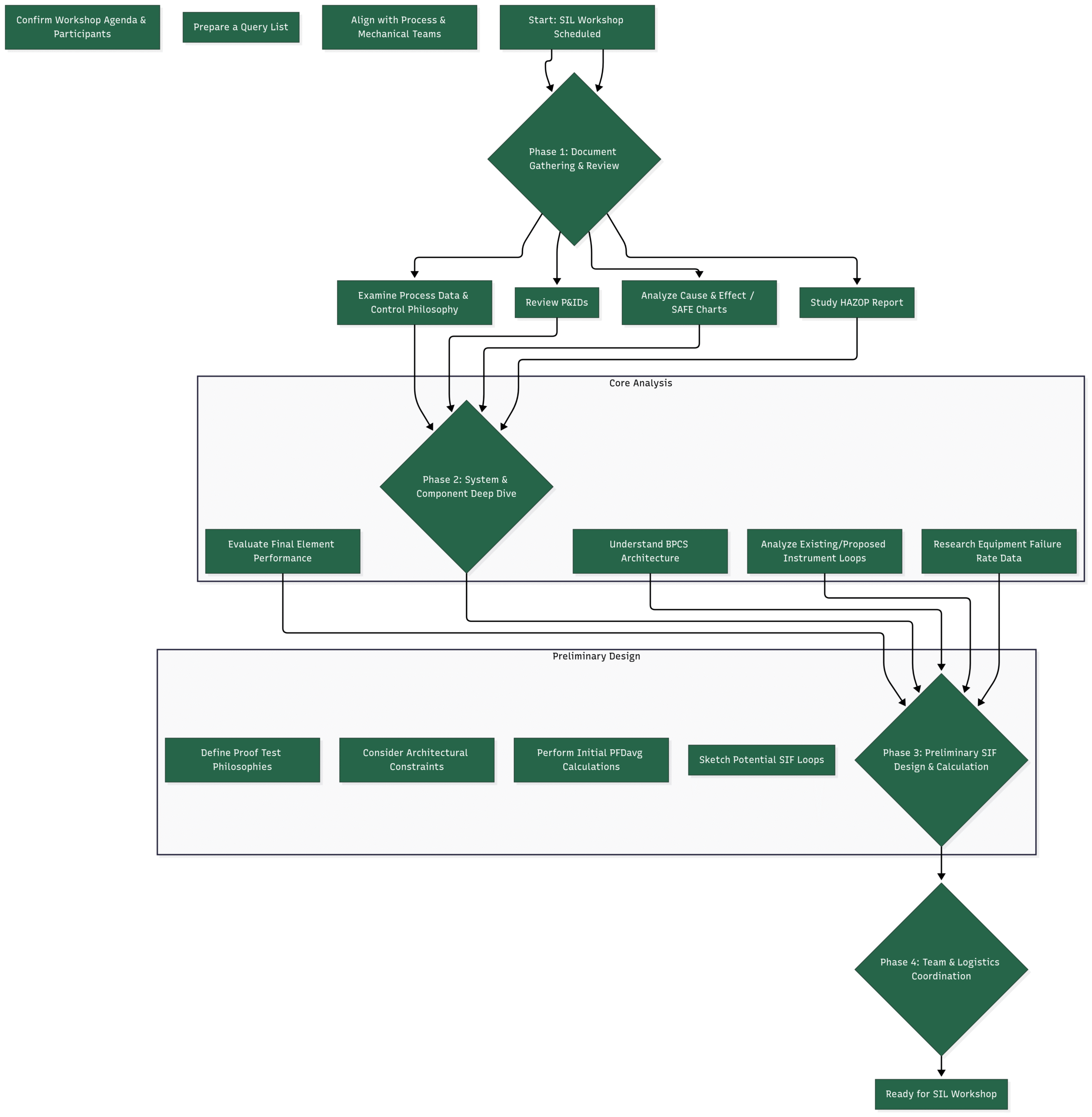
Phase 1: Document Gathering & Meticulous Review
This initial phase is about building your information arsenal. You need to become the single point of truth for all things instrumentation and control related to the hazardous scenarios being discussed.
✔️ Checklist Item 1: Piping and Instrumentation Diagrams (P&IDs)
The P&ID is your roadmap. Don’t just glance at it; immerse yourself in it.
Activity: Obtain the latest, “Issued for Design” or “As-Built” versions of all relevant P&IDs.
Action:
Trace every process line connected to the equipment under review.
Identify ALL instruments: transmitters (pressure, temperature, flow, level), control valves, shutdown valves, switches, and analyzers.
Highlight instruments that are part of the Basic Process Control System (BPCS) versus those that are already designated for safety systems.
Pay close attention to instrument locations (tappings, nozzles), as this can affect response time and accuracy.
Make notes directly on your copies. Question everything. Is that bypass valve normally open or closed? Is there a root valve for that transmitter?
✔️ Checklist Item 2: Cause & Effect (C&E) Diagrams / SAFE Charts
The C&E chart is the script for your plant’s automated responses. It links a cause (e.g., high pressure) to an effect (e.g., trip a pump, close a valve).
Activity: Scrutinize the C&E charts related to the process units being reviewed.
Action:
Cross-reference every input (cause) and output (effect) with the P&IDs. Ensure the tag numbers match perfectly. Discrepancies are red flags that must be resolved before the workshop.
Understand the logic. Is it a simple high-level trip, or is there complex voting logic involved (e.g., 2 out of 3)?
Identify which actions are performed by the BPCS and which are handled by a separate Safety Instrumented System (SIS). This distinction is fundamental to LOPA.
✔️ Checklist Item 3: HAZOP Report
The Hazard and Operability (HAZOP) study is the prequel to the SIL workshop. It identifies the “what-if” scenarios that you will be analyzing.
Activity: Read the entire HAZOP report, focusing on the nodes (sections of the plant) that are on the SIL workshop’s agenda.
Action:
For each high-risk scenario (deviation), identify the consequences and the existing safeguards.
Pay special attention to safeguards listed as “alarms” or “control loops.” The SIL team will need to determine if these are reliable enough to be considered Independent Protection Layers (IPLs).
Note any HAZOP actions assigned to the I&C discipline. Ensure they have been addressed or have a clear path to resolution.
✔️ Checklist Item 4: Control & Safeguarding Narratives / Philosophies
These documents provide the “why” behind the design shown on the P&IDs and C&E charts.
Activity: Obtain and read the process control narrative, shutdown philosophy, and any other relevant operating philosophies.
Action:
Understand the normal operating envelope of the process. What are the typical pressures, temperatures, and flows?
Learn the control strategies. Is a level controller a simple PI loop, or is it part of a complex cascade or feedforward scheme? This is crucial for assessing its effectiveness as a protection layer.
Identify the design basis for existing safety functions. Why was a particular trip point chosen? What was the intended response time?
Phase 2: System & Component Deep Dive
With the documentation reviewed, it’s time to dig into the hardware and system architecture. This is where your core I&C expertise shines.
✔️ Checklist Item 5: Understand the BPCS and SIS Architecture
You need to know the brain behind the operations.
Activity: Familiarize yourself with the Distributed Control System (DCS) and Safety Instrumented System (SIS) platforms.
Action:
What is the make and model of the DCS and SIS (e.g., Emerson DeltaV, Honeywell Experion PKS, Yokogawa Centum VP, HIMA HIMax)?
Crucially, are they physically and logically separate as required by IEC 61511?
What is the scan rate or cycle time of the controllers? This directly impacts the response time of any control loop or safety function.
How are alarms managed? Is there a dedicated alarm management system and philosophy?
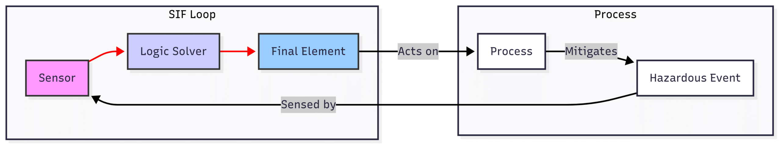
✔️ Checklist Item 6: Analyze Potential SIF Loops
A SIF is more than just a sensor; it’s a complete system. Before the workshop, you should already be thinking about how potential SIFs would be constructed. A typical SIF loop consists of three parts: the sensor, the logic solver, and the final element.
Activity: For each potential SIF identified from the HAZOP, start sketching out the components.
Action:
Sensors: What type of sensor is needed? A guided-wave radar for level? A differential pressure transmitter for flow? A gas detector? Consider the process conditions (pressure, temperature, corrosion) and required accuracy.
Logic Solver: This is the SIS controller.
Final Elements: This is most often a valve, but it could also be a pump trip, motor shutdown, or damper. What type of valve? Ball, globe, or gate? What type of actuator? Spring-return pneumatic? What is its fail state (fail-open or fail-close)?
✔️ Checklist Item 7: Research Equipment Reliability Data
The core of a SIL calculation is the Probability of Failure on Demand (PFD). This value is calculated using the failure rates of the SIF components. You must come to the workshop with realistic data.
Activity: Gather failure rate data for the types of instruments and final elements likely to be used.
Action:
Consult industry-standard databases like OREDA (Offshore and Onshore Reliability Data) or commercial sources like exida’s Safety Equipment Reliability Handbook (SERH).
If your company has its own historical maintenance records, use them! Plant-specific data is always preferable.
Find data for Dangerous Undetected (λ_DU) failures. These are the failures that prevent the SIF from working when a real demand occurs, and they are the primary driver of the PFD.
Be prepared to justify your numbers. Have the data sheets or database references handy.
Phase 3: Preliminary SIF Design & Calculation
This phase is proactive. Instead of waiting to be asked, you’ll come to the workshop with solutions and preliminary analyses already prepared. This will dramatically speed up the decision-making process.
✔️ Checklist Item 8: Sketch SIF Architectures
The SIL level heavily influences the required hardware architecture (or “voting arrangement”).
Activity: For high-risk scenarios that will likely require a SIL 2 or SIL 3 SIF, start sketching the architectural options.
Action:
1oo2 (one-out-of-two): Two instruments are installed. If either one detects the hazardous condition, the trip is initiated. This architecture is safer but more prone to spurious (false) trips.
2oo2 (two-out-of-two): Two instruments are installed. Both must detect the condition for the trip to occur. This reduces spurious trips but is less safe (a single failure renders it useless).
2oo3 (two-out-of-three): Three instruments are installed. The trip is initiated if at least two of them detect the condition. This is the gold standard for high-reliability systems, as it is tolerant of a single failure (safe or unsafe) and allows for online testing.
Be ready to discuss the pros and cons of each in the context of the specific application.
✔️ Checklist Item 9: Perform “Back-of-the-Envelope” PFDavg Calculations
You don’t need a finalized, certified report at this stage. But you do need to demonstrate feasibility. Use simplified equations to estimate the PFDavg (Average Probability of Failure on Demand) for your proposed SIFs.
Activity: Use your gathered failure rate data (λ_DU) and a proposed Proof Test Interval (TI) to estimate the PFDavg.
Action:
For a simple 1oo1 architecture, the simplified formula is:
Run a few scenarios. For example, what is the PFDavg for a SIF with a proposed Proof Test Interval (TI) of 1 year? What if the operations team can only realistically test it every 3 years? How does that impact the PFDavg and the achievable SIL?
Have a spreadsheet ready to perform these quick calculations during the workshop. This allows you to answer questions like, “Can we achieve SIL 2 with a single valve?” in real-time.
✔️ Checklist Item 10: Define Proof Test Philosophies
A SIF is only as good as its last test. The ability to perform a proof test is a critical design consideration.
Activity: For each potential SIF, think about how it will be proof-tested.
Action:
Can the sensor be tested in situ or does it need to be removed?
For final elements (valves), does it have a Partial Stroke Test (PST) device? PST is a game-changer for extending full proof test intervals and improving reliability.
What level of bypass is required to test the SIF while the plant is online? Will this require a maintenance override switch in the logic?
Estimate the time and personnel required to perform the test. This has a real impact on operational costs.
Phase 4: Team & Logistics Coordination
Finally, safety is a team sport. Your preparation is incomplete if it happens in a silo.
✔️ Checklist Item 11: Align with Other Disciplines
Talk to your colleagues before the workshop.
Activity: Schedule brief pre-meetings with key engineers from other disciplines.
Action:
Process Engineer: Confirm the trip setpoints, process deviation causes, and consequences. Understand their assumptions for the process safety time (the time from the initial deviation to the hazardous event). Your SIF must act faster than this time.
Mechanical Engineer: Discuss final element selection. Can the piping support the specified valve and actuator? Are there any material compatibility issues? What is the valve’s required stroke time?
Electrical Engineer: Confirm power supply arrangements for instruments and solenoids. Will they be powered from an Uninterruptible Power Supply (UPS)?
✔️ Checklist Item 12: Prepare a Query List
During your preparation, you will undoubtedly uncover discrepancies, gaps in information, or points that need clarification.
Activity: Maintain a running list of questions.
Action:
Organize your questions by topic (e.g., P&ID discrepancy, HAZOP safeguard clarification, operational assumption).
This demonstrates your diligence and helps make the workshop more efficient by addressing ambiguities early. Examples:
“The HAZOP lists a check valve as a safeguard against reverse flow, but the P&ID doesn’t show it. Can we confirm if it exists?”
“The cause & effect shows a trip at 10 bar, but the process narrative says the normal operating pressure is 9.5 bar. Is this margin sufficient?”
Conclusion: The Payoff of Preparation
Walking into a SIL workshop armed with this level of preparation is a transformative experience. You will be able to:
Provide immediate, data-backed answers.
Confidently propose feasible and reliable SIF designs.
Identify potential issues before they derail the meeting.
Collaborate effectively with the team to build a robust safety consensus.
Uphold your professional responsibility to ensure plant safety.
The time invested before the workshop pays dividends during it. You will not only contribute to a safer plant but also solidify your reputation as a knowledgeable and indispensable member of the engineering team. So, before your next SIL workshop, don’t just show up—show up prepared.