In today’s fast-paced industrial world, automation is king. 👑 At the heart of modern industrial automation lies a robust and reliable device: the Programmable Logic Controller (PLC). From massive automotive assembly lines to the local car wash, PLCs are the unseen brains making everything happen. But what exactly is inside this powerful little box? Understanding the core components of a PLC system is the first step to mastering automation.
This guide will break down the essential building blocks of a PLC, explaining what each part does and how they work together in perfect harmony to control complex industrial processes. We’ll explore everything from the central processor to the input/output modules that connect the PLC to the real world.
What is a Programmable Logic Controller (PLC)?
Before we dissect its components, let’s quickly define what a PLC is. A Programmable Logic Controller is a specialized industrial computer designed to control manufacturing processes, such as assembly lines, robotic devices, or any activity requiring high-reliability control and ease of programming.
Unlike a regular desktop computer, a PLC is built to withstand harsh industrial environments, including extreme temperatures, humidity, electrical noise, and vibration. Its primary function is to receive signals from input devices (like sensors and switches), execute a user-programmed logic, and send signals to output devices (like motors and valves).
Think of it as the central nervous system of a machine or process. It continuously monitors the state of input devices and makes decisions based on its custom program to control the state of output devices.
The 5 Core Components of a PLC System
A typical PLC system is not a single, monolithic block but a modular system composed of several key components working in unison. While the specific form factor can vary—from compact “brick” PLCs with fixed components to rack-mounted modular systems—the fundamental parts remain the same.
The five core components of any PLC system are:
The Central Processing Unit (CPU)
Memory (RAM, ROM, EEPROM)
Input/Output (I/O) Modules
The Power Supply
The Programming Device
Let’s dive deep into each of these essential parts.

1. The Central Processing Unit (CPU): The Brain of the Operation 🧠
The Central Processing Unit (CPU), often called the processor, is the heart and brain of the PLC system. It’s a microprocessor-based circuit that carries out all the computational and logical operations. If the PLC is the nervous system, the CPU is the brain, making all the critical decisions.
The CPU’s primary responsibility is to read data from input devices, execute the user-written control program stored in its memory, and then send appropriate commands to the output devices. This entire process happens in a continuous loop called the PLC scan cycle, which we’ll explore later.
Key Functions of the CPU:
Executing the Control Program: This is its main job. The CPU interprets and runs the logic defined by the user—be it Ladder Logic, Function Block Diagram (FBD), or another programming language.
Performing Mathematical Operations: Modern PLCs can handle everything from simple arithmetic (, , , ) to complex floating-point calculations required for process control loops (e.g., PID control).
Handling Communication: The CPU manages communication with other devices, such as other PLCs, Human-Machine Interfaces (HMIs), SCADA systems, and the programming device.
Running Diagnostics: The CPU constantly monitors the health of the entire PLC system. It checks for hardware failures, communication errors, and syntax errors in the user program, and can alert operators through fault indicators or messages.
The power of a PLC is largely determined by its CPU. Key performance indicators for a PLC processor include its scan time (the time it takes to complete one scan cycle, typically measured in milliseconds), its memory capacity, and the number and type of communication ports it supports. A faster CPU can make decisions more quickly, which is critical for high-speed applications like packaging or motion control.
2. Memory: Storing the Program and Data 💾
Just like any computer, a PLC needs memory to store information. This memory is where the user’s control program, system configuration, and operational data are kept. PLC memory is non-volatile, meaning it retains its contents even when power is turned off. This is crucial for industrial applications, as a power outage shouldn’t erase the control logic.
PLC memory can be divided into several types, each serving a specific purpose.
Types of PLC Memory:
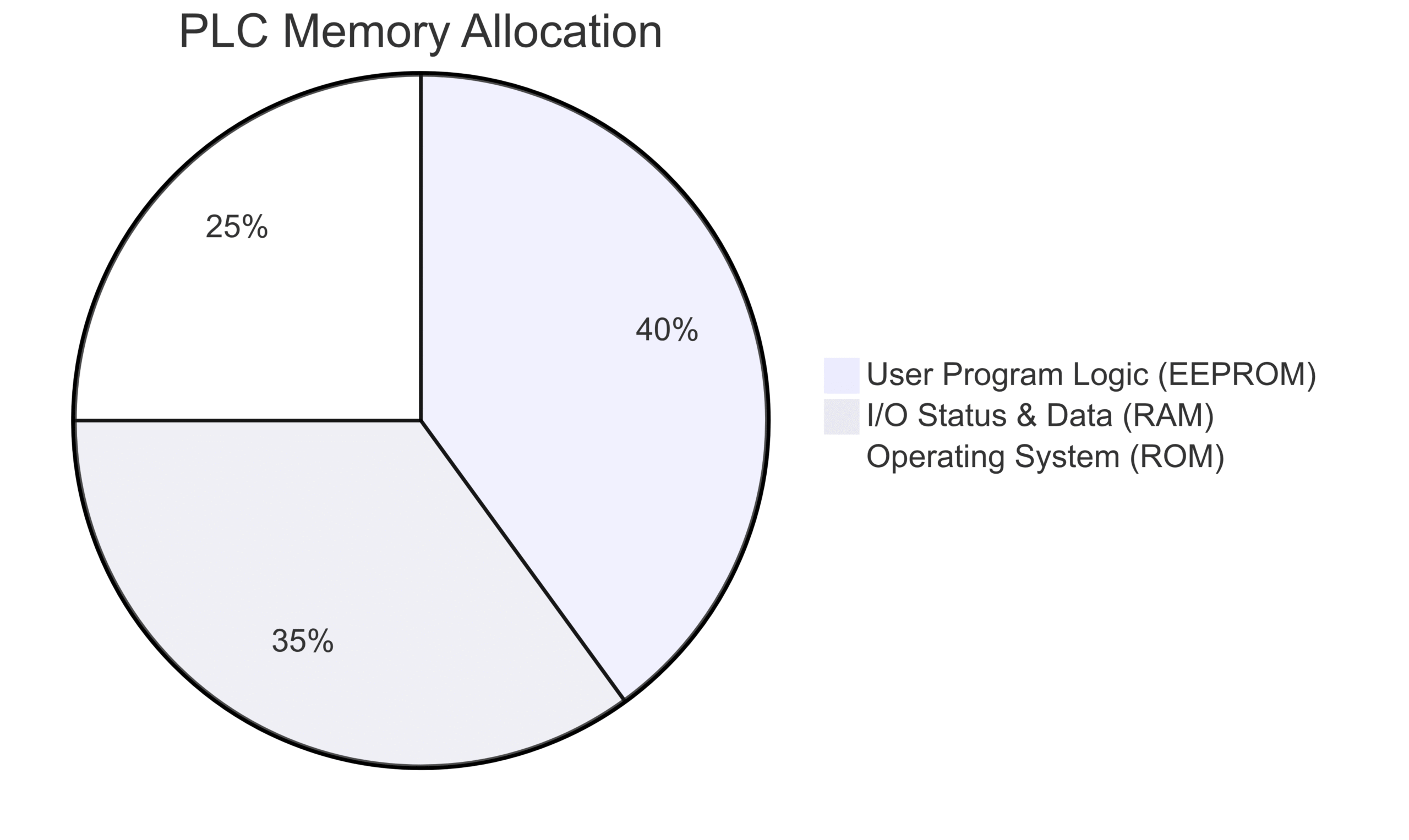
Read-Only Memory (ROM): This memory stores the PLC’s operating system firmware. It’s written at the factory and cannot be altered by the user. The OS manages the core functions of the PLC, including how it boots up, runs diagnostics, and executes the scan cycle.
Random-Access Memory (RAM): This is the PLC’s working memory. It’s where the CPU stores temporary information about the status of inputs and outputs, timer and counter values, and other operational data. In many PLCs, the user’s application program is loaded into RAM for execution because it allows for faster access speeds. While some RAM is volatile, PLCs use a backup battery or supercapacitor to retain the data in this RAM during power loss.
Electrically Erasable Programmable Read-Only Memory (EEPROM): This is a type of non-volatile memory used to store the user’s control program and important configuration data. The “Electrically Erasable” part means the user can easily modify the program from a programming device without needing to remove the memory chip. This is the most common type of memory for storing the final application logic.
The memory architecture of a PLC is designed for reliability. It separates the vital operating system (in ROM) from the user application (in RAM/EEPROM), ensuring that a programming error can’t corrupt the fundamental operation of the PLC itself.
3. Input/Output (I/O) Modules: The Connection to the Real World 🌐
The CPU and memory are the brains, but they are blind and deaf without the Input/Output (I/O) Modules. These modules are the PLC’s senses and hands, providing the physical connection between the central processor and the industrial equipment it controls.
Input Modules detect signals from the outside world (sensors, switches, buttons) and convert them into a logic signal that the CPU can understand (typically 5V DC).
Output Modules take the control signals from the CPU and convert them into a voltage or current level that can power an output device (motors, lights, solenoids, valves).
This separation is vital for protecting the sensitive microprocessor in the CPU from the high voltages and electrical noise common on the factory floor. This electrical isolation is typically achieved using opto-isolators, which use light to transmit the signal across a gap, preventing electrical surges from damaging the PLC’s brain.
I/O modules come in two main flavors: Discrete (Digital) and Analog.
Discrete (Digital) I/O
Discrete I/O, also known as Digital I/O, deals with signals that have only two states: ON or OFF. It’s a binary system (1 or 0).
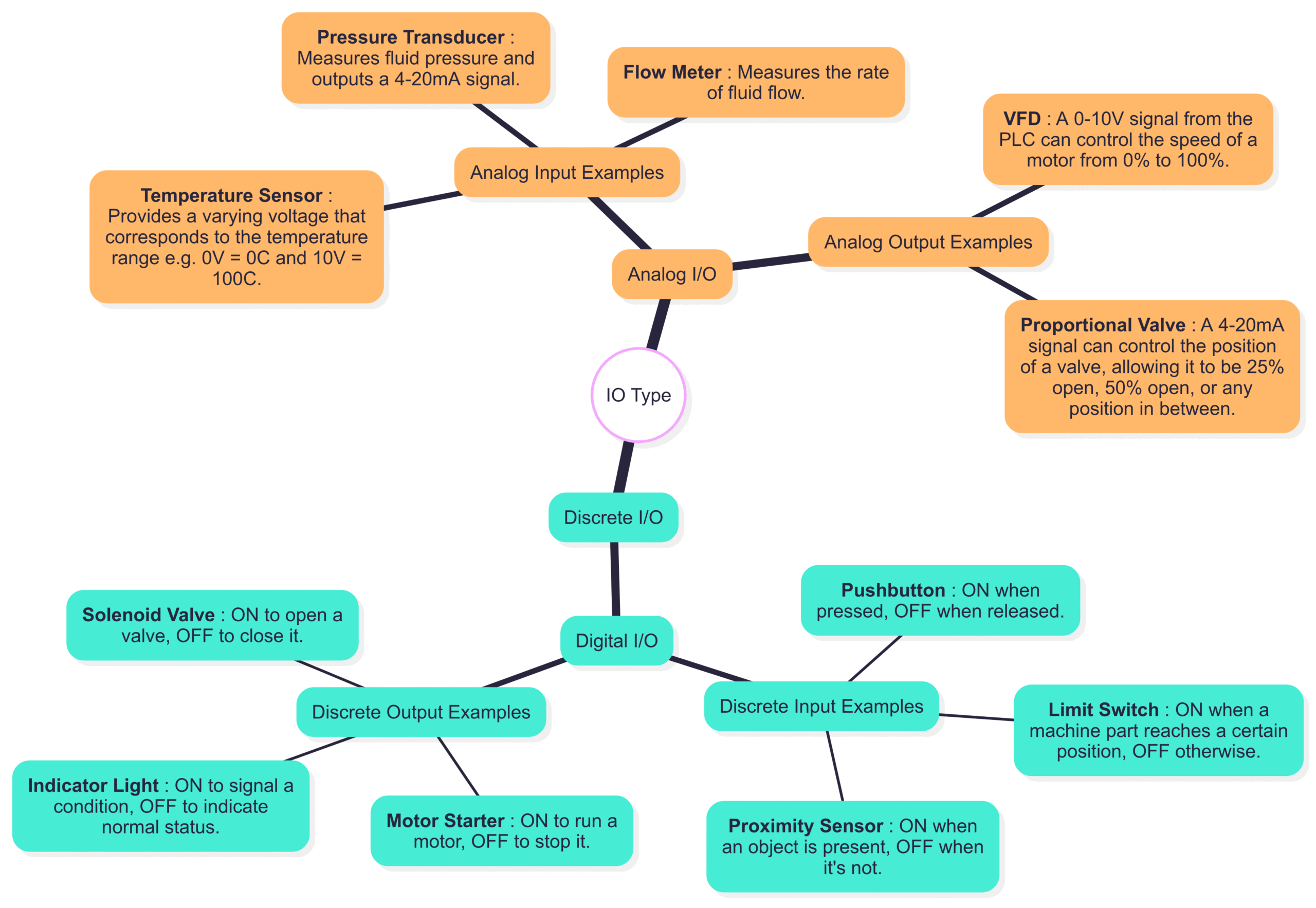
Discrete Input Examples:
Proximity Sensor: ON when an object is present, OFF when it’s not.
Pushbutton: ON when pressed, OFF when released.
Limit Switch: ON when a machine part reaches a certain position, OFF otherwise.
Discrete Output Examples:
Motor Starter: ON to run a motor, OFF to stop it.
Indicator Light: ON to signal a condition, OFF to indicate normal status.
Solenoid Valve: ON to open a valve, OFF to close it.
Analog I/O
Analog I/O deals with signals that can vary continuously over a range. This is necessary for measuring and controlling processes that require precision beyond a simple ON/OFF state. These signals are typically represented as a variable voltage (e.g., 0-10V) or current (e.g., 4-20mA).
Analog Input Examples:
Temperature Sensor: Provides a varying voltage that corresponds to the temperature range (e.g., 0V = 0°C, 10V = 100°C).
Pressure Transducer: Measures fluid pressure and outputs a 4-20mA signal.
Flow Meter: Measures the rate of fluid flow.
Analog Output Examples:
Variable Frequency Drive (VFD): A 0-10V signal from the PLC can control the speed of a motor from 0% to 100%.
Proportional Valve: A 4-20mA signal can control the position of a valve, allowing it to be 25% open, 50% open, or any position in between.
Modern PLC systems are highly modular, allowing users to mix and match different types and quantities of I/O modules on a rack to perfectly suit the specific application.
4. The Power Supply: Energizing the System ⚡
The Power Supply is an often-overlooked but absolutely critical component. Its job is simple but essential: it takes the standard AC line voltage (e.g., 120V AC or 240V AC) available in the plant and converts it into the low-voltage DC power required by the PLC’s internal components.
The CPU, memory, and I/O module circuitry typically run on low-voltage DC, such as 24V DC, 5V DC, or 3.3V DC. The power supply provides this clean, stable, and regulated DC voltage.
Key Functions of the Power Supply:
Voltage Conversion: Steps down high AC voltage to low DC voltage.
Voltage Regulation: Ensures the output DC voltage remains constant even if the input AC voltage fluctuates, protecting the sensitive electronics from sags and surges.
Filtering: Cleans the power of electrical noise that could interfere with the PLC’s operation.
Backup Power Management: In some systems, the power supply also manages the charging of a backup battery or supercapacitor that keeps the RAM alive during a power failure.
A reliable power supply is fundamental to the overall reliability of the PLC system. A failing power supply can cause unpredictable behavior, random shutdowns, and system faults that are often difficult to diagnose. For critical applications, redundant power supplies are often used, where a second power supply automatically takes over if the primary one fails.
5. The Programming Device: The Human Interface 💻
The final core component is the Programming Device. This is the tool that allows humans to interact with the PLC. It’s used to create, edit, download, and troubleshoot the control logic program.
In the early days of PLCs, these were dedicated, proprietary handheld terminals. Today, the most common programming device is a standard laptop or desktop computer running specialized software provided by the PLC manufacturer (e.g., Rockwell’s Studio 5000, Siemens’ TIA Portal, or Schneider’s EcoStruxure Control Expert).
Functions of the Programming Device Software:
Program Development: Provides an editor for writing the control logic in one of the standard IEC 61131-3 programming languages:
Ladder Logic (LD): The most popular language, it mimics electrical relay-based control circuits.
Function Block Diagram (FBD): A graphical language that connects blocks of functions.
Structured Text (ST): A high-level, text-based language similar to Pascal or C.
Instruction List (IL): A low-level, assembler-like language.
Sequential Function Chart (SFC): A graphical language for describing sequential processes.
Downloading/Uploading: Transfers the created program to the PLC’s memory (downloading) and retrieves the program currently in the PLC (uploading).
Monitoring and Debugging: This is one of the most powerful features. The software allows engineers to go “online” with the PLC and monitor the program’s execution in real-time. They can see the status of inputs, the logic being solved, and the state of outputs. This is invaluable for troubleshooting machine faults and commissioning new systems.
Configuration: Used to set up the PLC’s hardware configuration, including the types of I/O modules installed, communication settings, and other system parameters.
The programming device is typically only connected when programming or troubleshooting is needed. Once the program is downloaded and verified, the PLC runs independently without the device attached.
How PLC Components Work Together: The PLC Scan Cycle
Now that we know the individual players, how do they work together as a team? The magic happens in a continuous, repetitive process called the PLC Scan Cycle. The CPU performs this cycle thousands of times per second.
The scan cycle consists of four main steps:
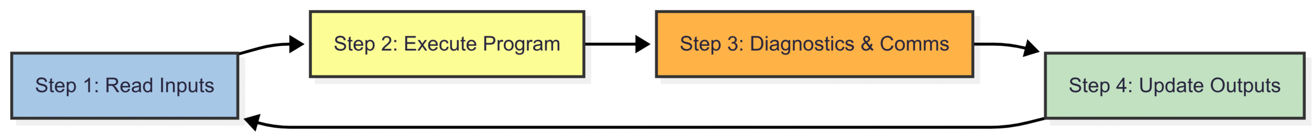
Step 1: Read Inputs: The CPU begins the scan by reading the status of every input connected to the input modules. It takes a snapshot of all input states (ON/OFF, or analog values) and stores this information in a section of RAM called the Input Image Table.
Step 2: Execute Program: The CPU then executes the user’s control program, one instruction at a time, from top to bottom. It makes logical decisions based on the input states stored in the Input Image Table. As it solves the logic, it determines what the state of the outputs should be and stores these results in a separate area of RAM called the Output Image Table.
Step 3: Diagnostics and Communication: During the scan, the CPU performs internal diagnostic checks to ensure the hardware and software are running correctly. It also handles any communication requests, such as talking to an HMI or another PLC.
Step 4: Update Outputs: After the program has been fully executed, the CPU takes the data from the Output Image Table and updates the state of all the physical output devices connected to the output modules. The lights turn on, the motors start, and the valves open.
Once Step 4 is complete, the cycle immediately begins again at Step 1. The time it takes to complete one full cycle is the scan time. For most applications, this time is incredibly short, ranging from 1 to 100 milliseconds. This high speed makes it seem like the PLC is reacting instantaneously, even though it’s following this sequential process.
Conclusion
The Programmable Logic Controller is a masterpiece of industrial engineering, combining robustness with flexibility. While it may seem like a complex “black box,” it’s built from a set of logical, understandable core components.
By breaking it down, we can see how the CPU acts as the brain, the Memory holds the instructions, the Power Supply provides the energy, and the I/O Modules form the bridge to the physical world. All of this is orchestrated by a human engineer using a Programming Device. Together, these five components create a powerful system that has become the backbone of modern manufacturing and automation, ensuring our world runs efficiently, safely, and reliably.