The Critical Importance of Accurate Gas Flow Measurement
Before we embark on our exploration of different flow meter technologies, it’s crucial to understand why precision in gas flow measurement is paramount. Inaccurate readings can lead to a cascade of negative consequences, including:
- Financial Losses: In custody transfer applications, even a small measurement error can translate into significant financial discrepancies between buyers and sellers.
- Process Inefficiency: Many industrial processes rely on precise gas ratios. Incorrect flow measurements can lead to suboptimal reactions, reduced yield, and wasted resources.
- Safety Hazards: In applications involving combustible or hazardous gases, inaccurate flow monitoring can create dangerous conditions, potentially leading to explosions or toxic exposures.
- Environmental Non-Compliance: Emissions monitoring requires accurate flow data to ensure adherence to environmental regulations.
- Poor Product Quality: In industries like food and beverage or pharmaceuticals, the precise control of gas flow is often directly linked to the quality and consistency of the final product.
With these stakes in mind, let’s examine the leading contenders in the realm of gas flow measurement.
1. Coriolis Flow Meters: The Gold Standard of Accuracy
When unparalleled accuracy is non-negotiable, Coriolis flow meters stand in a class of their own. These sophisticated instruments directly measure the mass flow rate of a gas, independent of its pressure, temperature, and composition. This intrinsic ability to measure mass makes them a top choice for critical applications where precision is paramount.
Principle of Operation
The operation of a Coriolis flow meter is based on the Coriolis effect, a phenomenon observed in a rotating frame of reference.
Block Diagram of a Coriolis Flow Meter:
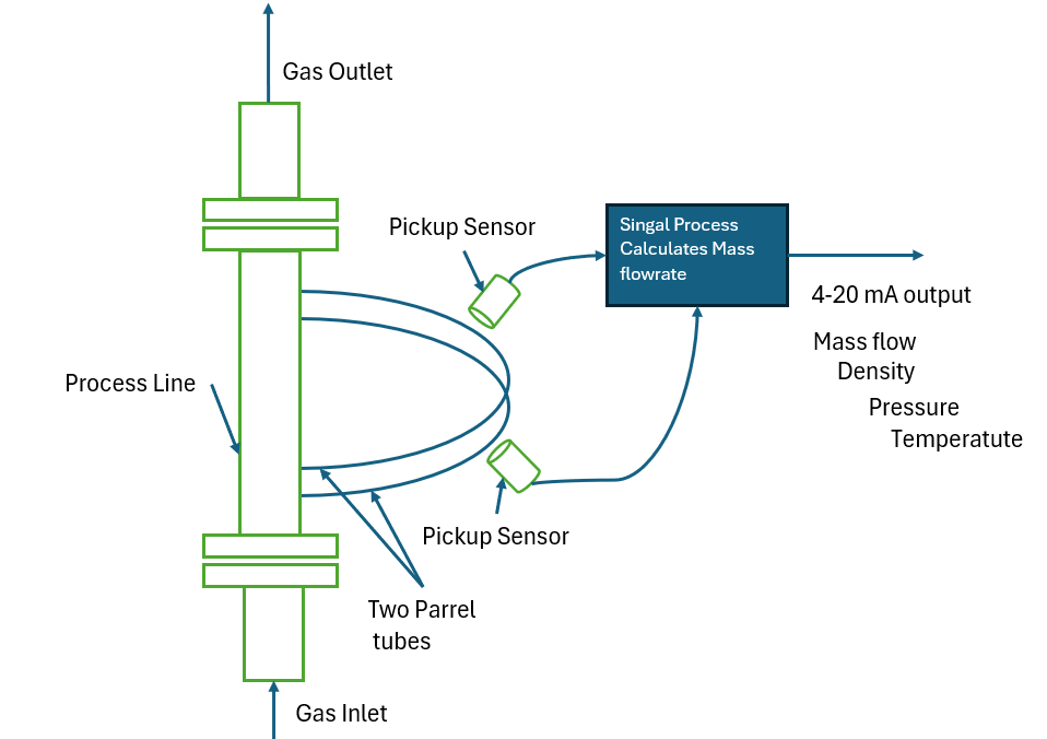
- Flow Path: The incoming gas is split and directed through two parallel tubes, typically U-shaped or straight.
- Vibration: A drive coil causes these tubes to vibrate at their natural resonant frequency.
- Coriolis Effect: As the gas flows through the vibrating tubes, the Coriolis effect causes the tubes to twist. The amount of twist is directly proportional to the mass flow rate of the gas.
- Sensor Detection: Sensors placed at the inlet and outlet of the vibrating tubes detect the phase shift (the tiny time difference) in the vibration caused by the twist.
- Signal Processing: A transmitter processes the sensor signals to calculate the mass flow rate with exceptional accuracy. It can also simultaneously measure the density and temperature of the gas.
Pros and Cons for Gas Measurement
Advantages:
- Highest Accuracy: Offers the best accuracy and repeatability of any flow meter technology for gases.
- Direct Mass Flow Measurement: Eliminates the need for pressure and temperature compensation, simplifying the measurement process.
- Multi-Parameter Measurement: Provides simultaneous measurement of mass flow, density, and temperature.
- Gas Composition Independence: The measurement is unaffected by changes in gas composition.
- High Turndown Ratio: Can accurately measure a wide range of flow rates.
Disadvantages:
- High Initial Cost: Coriolis meters are among the most expensive flow meter types.
- Pressure Drop: The design can introduce a pressure drop in the gas line, which may not be suitable for all applications.
- Sensitivity to Vibrations: External vibrations can potentially interfere with the measurement, although modern designs have significantly mitigated this issue.
- Limited in Low-Density Gases: Performance can be limited in very low-pressure or low-density gas applications.
Ideal Applications
- Custody transfer of natural gas and other valuable gases.
- Critical process control in the chemical and petrochemical industries.
- Hydrogen and specialty gas measurement.
- Filling and dosing applications requiring high precision.
2. Thermal Mass Flow Meters: A Versatile and Cost-Effective Solution
Thermal mass flow meters have gained widespread popularity for their ability to directly measure the mass flow of a wide range of clean, dry gases. They are a cost-effective alternative to Coriolis meters in many applications and offer excellent accuracy and repeatability.
Principle of Operation
Thermal mass flow meters operate on the principle of heat transfer. The rate at which heat is carried away by a flowing gas is directly proportional to its mass flow rate.
Block Diagram of a Thermal Mass Flow Meter:
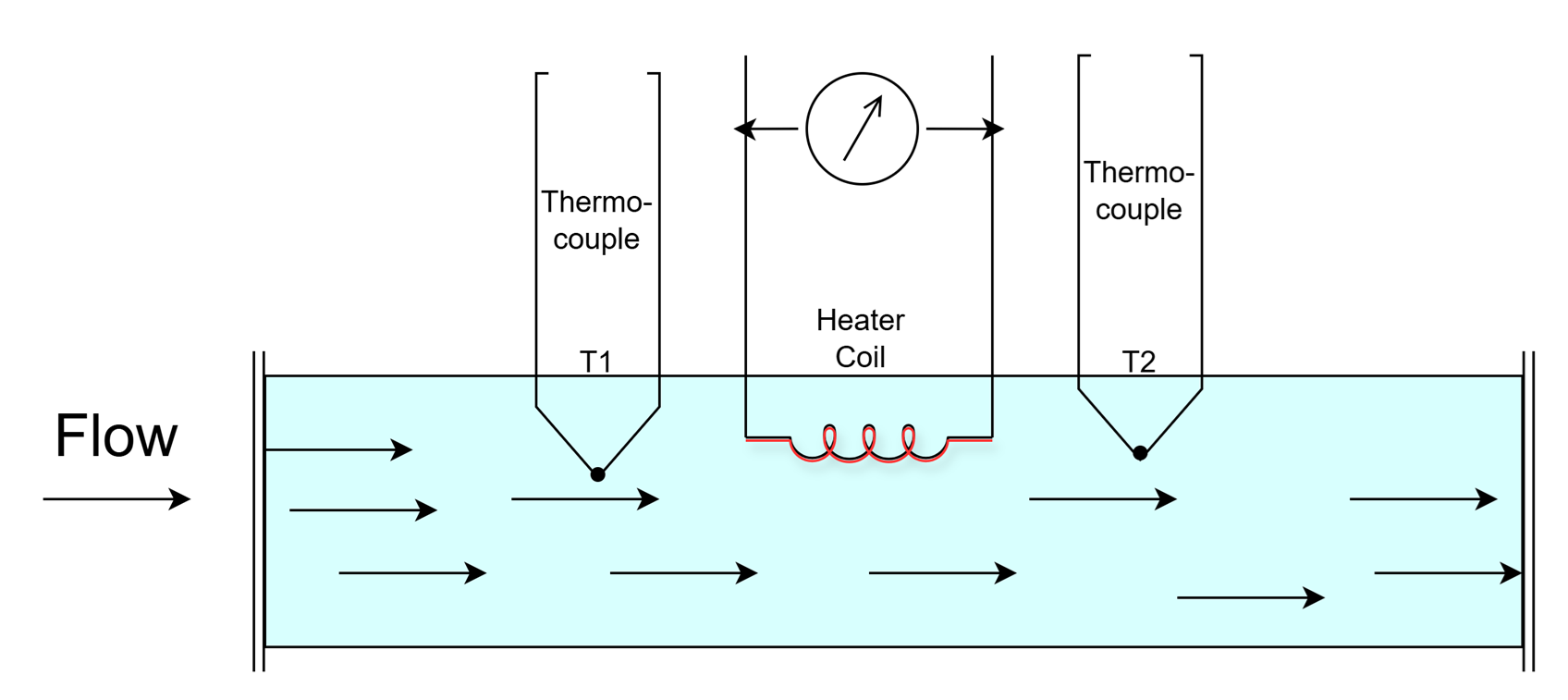
- Heated and Reference Sensors: The meter consists of two primary sensors: a heated sensor and a reference temperature sensor.
- Heat Transfer: The heated sensor is maintained at a constant temperature differential above the reference sensor, which measures the gas temperature.
- Cooling Effect: As gas flows past the heated sensor, it carries away heat, causing a cooling effect.
- Power Compensation: To maintain the constant temperature differential, the instrument’s circuitry must supply more power to the heated sensor.
- Mass Flow Calculation: The amount of additional power required is directly proportional to the mass flow rate of the gas. The transmitter uses this information to calculate and output the mass flow.
Pros and Cons for Gas Measurement
Advantages:
- Direct Mass Flow Measurement: Provides a direct reading of mass flow without the need for external pressure and temperature compensation.
- High Accuracy and Repeatability: Offers excellent performance for clean gases.
- Wide Turndown Ratio: Can accurately measure a broad range of flow rates.
- Low Pressure Drop: Insertion-style thermal mass flow meters have a negligible impact on line pressure.
- Cost-Effective: Generally more affordable than Coriolis meters.
Disadvantages:
- Gas Composition Dependency: The measurement is dependent on the thermal properties of the gas. A change in gas composition from what the meter was calibrated for will result in inaccurate readings.
- Susceptible to Moisture and Particulates: The presence of moisture or particulates in the gas stream can affect the heat transfer and lead to inaccuracies or sensor fouling.
- Not Suitable for Wet or Dirty Gases: Best suited for clean, dry gas applications.
Ideal Applications
- Compressed air monitoring and leak detection.
- Natural gas sub-metering for industrial furnaces and boilers.
- Aeration control in wastewater treatment plants.
- Nitrogen and argon blanketing in industrial processes.
- Semiconductor manufacturing processes.
3. Ultrasonic Flow Meters: Non-Intrusive and Ideal for Large Pipes
Ultrasonic flow meters are a non-intrusive and highly versatile technology for measuring the volumetric flow rate of gases, particularly in large pipelines. Their ability to be clamped onto the outside of a pipe without process shutdown makes them an attractive option for many applications.
Principle of Operation
Ultrasonic flow meters utilize the principle of transit time difference. Sound waves are transmitted through the flowing gas, and the time it takes for the sound to travel with and against the flow is measured.
Block Diagram of an Ultrasonic Flow Meter (Transit Time):
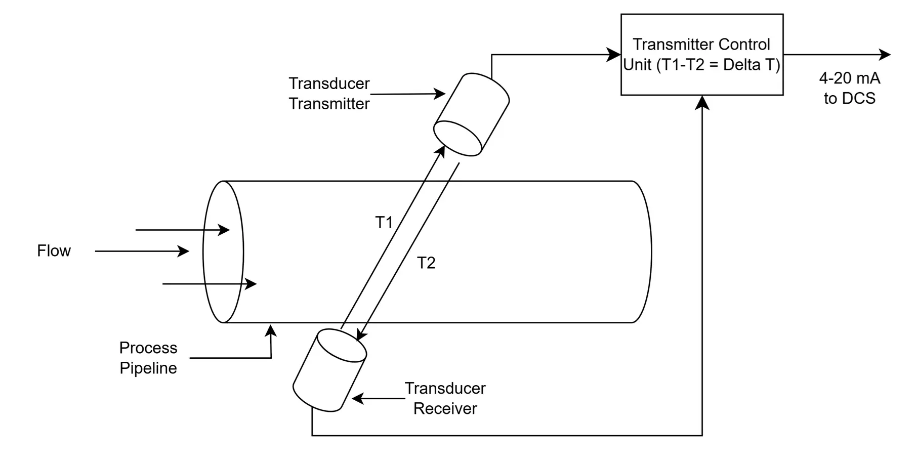
- Transducers: Two ultrasonic transducers are mounted on the pipe, one upstream and one downstream.
- Signal Transmission: The transducers act as both transmitters and receivers, sending ultrasonic pulses through the gas.
- Transit Time Measurement: The meter measures the time it takes for the signal to travel from the upstream transducer to the downstream transducer (
t_AB) and the time it takes to travel from the downstream transducer to the upstream transducer (t_BA). - Flow Velocity Calculation: The sound wave traveling with the flow moves faster than the one traveling against it. The difference in transit times (
t_BA - t_AB) is directly proportional to the velocity of the gas. - Volumetric Flow Calculation: The transmitter uses the calculated velocity and the cross-sectional area of the pipe to determine the volumetric flow rate.
Pros and Cons for Gas Measurement
Advantages:
- Non-Intrusive: Clamp-on models can be installed without cutting the pipe or shutting down the process.
- No Pressure Drop: As there are no obstructions in the flow path, there is no pressure loss.
- Suitable for Large Pipes: An excellent choice for large-diameter pipelines where other technologies may be impractical or expensive.
- Low Maintenance: No moving parts to wear out.
- Bidirectional Flow Measurement: Can measure flow in both directions.
Disadvantages:
- Requires a Well-Developed Flow Profile: Accuracy can be affected by turbulence, requiring straight pipe runs upstream and downstream of the meter.
- Sensitive to Acoustic Noise: High levels of acoustic noise in the pipeline can interfere with the measurement.
- Gas Properties Can Affect Accuracy: Changes in gas density and temperature can impact the speed of sound and affect accuracy, though many modern meters have built-in compensation.
- Higher Initial Cost for Custody Transfer Models: High-accuracy, multi-path ultrasonic meters for custody transfer can be expensive.
Ideal Applications
- Custody transfer of natural gas in large pipelines.
- Flare gas measurement.
- Check metering and allocation measurement.
- Large-scale industrial gas distribution.
4. Vortex Flow Meters: Robust and Reliable for Steam and Gas
Vortex flow meters are a robust and reliable technology for measuring the volumetric flow of gases, steam, and low-viscosity liquids. They have no moving parts and are well-suited for a wide range of industrial applications.
Principle of Operation
Vortex flow meters operate on the principle of vortex shedding. When a fluid flows past a bluff body (a shedder bar), it creates alternating vortices downstream.
Block Diagram of a Vortex Flow Meter:
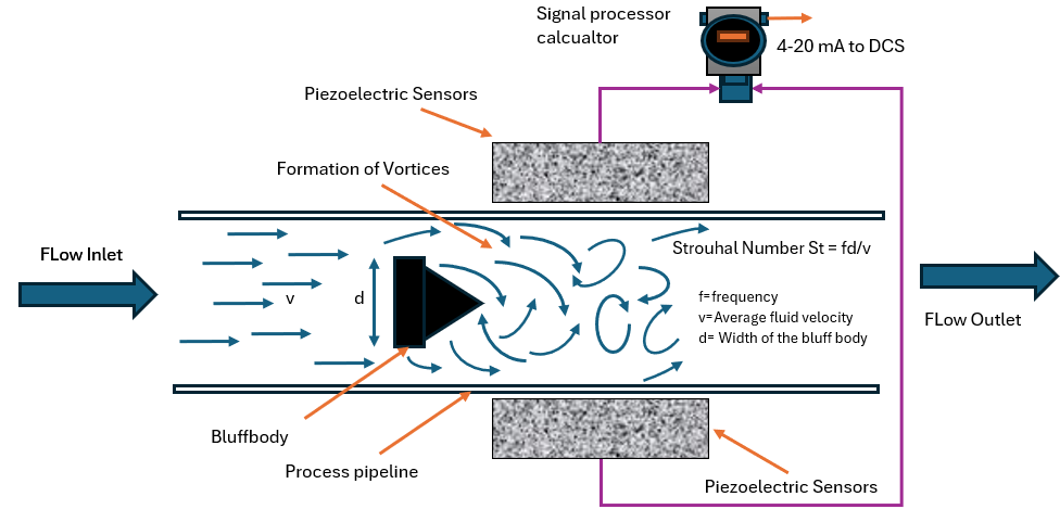
- Bluff Body: A shedder bar is placed in the flow path.
- Vortex Shedding: As the gas flows past the shedder bar, it creates a series of alternating vortices on either side of the bar. This phenomenon is known as the von Kármán vortex street.
- Frequency Proportional to Velocity: The frequency at which these vortices are shed is directly proportional to the velocity of the gas.
- Vortex Detection: A sensor, typically a piezoelectric crystal, detects the pressure fluctuations caused by the vortices.
- Flow Rate Calculation: The transmitter converts the frequency of the vortices into a volumetric flow rate.
Pros and Cons for Gas Measurement
Advantages:
- No Moving Parts: Low maintenance and high reliability.
- Wide Application Range: Suitable for gases, steam, and conductive and non-conductive liquids.
- Good Accuracy: Provides accurate and repeatable measurements.
- Wide Temperature and Pressure Range: Can operate under demanding process conditions.
Disadvantages:
- Requires a Minimum Flow Rate: Not suitable for very low flow applications as vortices may not form properly.
- Pressure Drop: The shedder bar creates a pressure drop in the line.
- Requires Straight Pipe Runs: Susceptible to inaccuracies caused by distorted flow profiles.
- Sensitivity to Vibrations: Pipe vibrations at the same frequency as the vortex shedding can cause errors.
Ideal Applications
- Steam flow measurement.
- General-purpose gas flow monitoring in industrial plants.
- Compressed air measurement.
- Measurement of hot gases and aggressive fluids.
5. Differential Pressure (DP) Flow Meters: The Tried and True Workhorse
Differential pressure flow meters are one of the oldest and most widely used technologies for gas flow measurement. They are based on Bernoulli’s principle, which states that as the velocity of a fluid increases, its pressure decreases.
Principle of Operation
DP meters work by introducing a constriction in the pipe, which creates a pressure drop. This pressure drop is then measured and correlated to the flow rate.
Block Diagram of a Differential Pressure Flow Meter (with Orifice Plate):
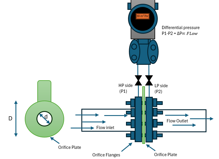
- Primary Element: A primary element, such as an orifice plate, venturi tube, or flow nozzle, is installed in the pipeline to create a restriction.
- Pressure Drop: As the gas flows through the restriction, its velocity increases, and its pressure decreases.
- Pressure Measurement: Pressure taps are located upstream and downstream of the primary element to measure the pressure difference (P1 – P2).
- Flow Rate Calculation: The differential pressure is proportional to the square of the flow velocity. A DP transmitter measures this pressure difference and calculates the volumetric flow rate.
Pros and Cons for Gas Measurement
Advantages:
- Low Initial Cost: DP meters, particularly those with orifice plates, are relatively inexpensive.
- Well-Understood Technology: A vast body of knowledge and standards exists for their application.
- Suitable for a Wide Range of Gases and Conditions: Can be used in various applications with different gases, temperatures, and pressures.
Disadvantages:
- Non-Linear Output: The relationship between differential pressure and flow rate is non-linear, which can limit the turndown ratio.
- Permanent Pressure Loss: All DP meters introduce a permanent pressure loss in the system.
- Accuracy Can Be Affected by Wear: The primary element can wear over time, affecting accuracy.
- Requires Straight Pipe Runs: Highly sensitive to flow profile distortions.
Ideal Applications
- Basic flow monitoring where high accuracy is not the primary concern.
- Well-established applications with stable flow conditions.
- When a low-cost solution is a priority.
6. Positive Displacement (PD) Flow Meters: High Accuracy for Billing and Custody Transfer
Positive displacement flow meters are highly accurate volumetric flow meters that are commonly used for custody transfer and billing of natural gas, especially in residential and commercial settings.
Principle of Operation
PD meters operate by trapping a precise volume of gas and then passing it downstream. The total flow is determined by counting the number of trapped volumes that pass through the meter.
Block Diagram of a Rotary Gas Meter (a type of PD meter):
      [Gas Inlet] -> [Measuring Chamber with Two Intermeshing Impellers] -> [Gas Outlet]
                            |
           [Rotation of Impellers (Driven by Gas Flow)]
                            |
           [Gear Train and Register (Counts Rotations)]
                            |
                            v
                    [Output: Totalized Volume]
- Measuring Chamber: The meter has a precisely machined measuring chamber containing rotating components like impellers, gears, or pistons.
- Trapping and Displacing: As gas flows through the meter, it forces the rotating components to move, trapping and displacing a known volume of gas with each rotation.
- Counting Rotations: A gear train and register mechanism count the number of rotations.
- Totalized Volume: The total volume of gas that has passed through the meter is displayed on a mechanical or electronic register.
Pros and Cons for Gas Measurement
Advantages:
- High Accuracy: Provides excellent accuracy, especially at low flow rates.
- High Repeatability: Consistently delivers precise measurements.
- No Straight Pipe Requirements: Installation is not dependent on long straight pipe runs.
- Reliable and Long-Lasting: With proper maintenance, PD meters are very reliable.
Disadvantages:
- Moving Parts: The presence of moving parts makes them susceptible to wear and tear, especially with dirty gas.
- Pressure Drop: Can introduce a significant pressure drop.
- Potential for Blockage: Can be damaged by particulates in the gas stream.
- Bulky and Heavy: Can be larger and heavier than other meter types.
Ideal Applications
- Natural gas billing for residential and commercial customers.
- Custody transfer of natural gas at smaller distribution points.
- Applications requiring high accuracy at low to moderate flow rates.
7. Turbine Flow Meters: A Reliable Choice for High-Volume Gas Measurement
Turbine flow meters are a well-established and reliable technology for measuring the volumetric flow of clean, high-velocity gases. They are commonly used in the natural gas industry for custody transfer and fiscal measurement.
Principle of Operation
Turbine meters use the kinetic energy of the flowing gas to rotate a turbine rotor. The speed of the rotor’s rotation is proportional to the gas velocity.
Block Diagram of a Turbine Flow Meter:
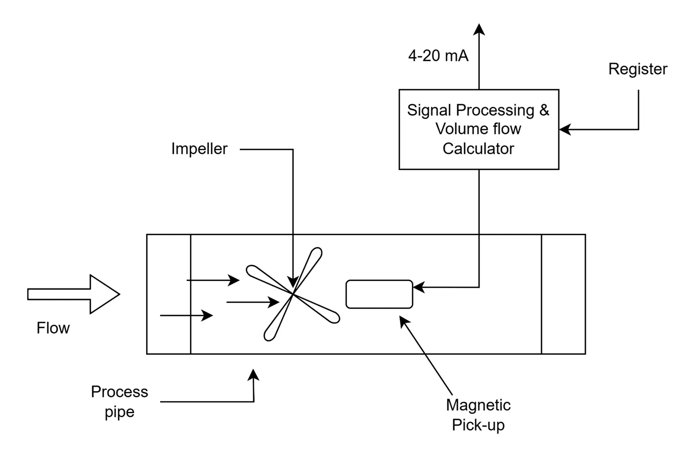
- Rotor Assembly: The core of the meter is a multi-bladed rotor that is free to rotate in the gas stream.
- Rotation: The flowing gas impinges on the turbine blades, causing the rotor to spin.
- Rotational Speed Proportional to Velocity: The rotational speed of the rotor is directly proportional to the gas velocity.
- Blade Passage Detection: A pickup sensor (magnetic or modulated carrier) detects the passage of each turbine blade.
- Flow Rate Calculation: The transmitter converts the frequency of the blade passages into a volumetric flow rate.
Pros and Cons for Gas Measurement
Advantages:
- High Accuracy and Repeatability: Offers excellent performance in clean gas applications.
- Good Turndown Ratio: Can measure a wide range of flow rates.
- Relatively Low Pressure Drop: Has a lower pressure drop compared to some other meter types.
- Cost-Effective for High-Volume Measurement: A good value proposition for large-volume applications.
Disadvantages:
- Moving Parts: The rotor and bearings are subject to wear and require periodic maintenance.
- Requires Clean Gas: Particulates in the gas can damage the rotor and affect accuracy.
- Requires Straight Pipe Runs: Performance can be affected by flow profile distortions.
Ideal Applications
- Custody transfer of natural gas in transmission and distribution systems.
- Fiscal measurement of natural gas.
- Large industrial gas consumption monitoring.
Choosing the Right Flow Meter: A Summary of Key Considerations
Selecting the best flow meter for your gas measurement application requires a careful evaluation of several factors:
Conclusion: A Strategic Decision for Optimal Performance
The journey to selecting the ideal gas flow meter is not about finding a single “best” solution, but rather about identifying the technology that best aligns with the specific demands of your application. By understanding the fundamental principles of operation, the inherent advantages and disadvantages, and the ideal use cases for each type of flow meter, you can make a strategic decision that will ensure accuracy, efficiency, and safety in your gas measurement processes for years to come.
This professional’s guide has provided a comprehensive roadmap to navigate the diverse landscape of gas flow meter technologies. Armed with this knowledge, you are now better equipped to engage with vendors, evaluate specifications, and ultimately, select the perfect instrument to meet your professional needs and contribute to the success of your operations.