
The Ultimate Guide: A Deep Dive into the 3D 90% Modelling Review
The 90% 3D model review is arguably one of the most critical milestones in any industrial engineering project. It represents the final, comprehensive check-up before engineering drawings are stamped “Issued for Construction” (IFC). Getting this review right prevents costly rework, schedule delays, and safety hazards on site. It’s the moment where the digital twin is stress-tested against the realities of construction, operation, and maintenance.
This guide provides a detailed, discipline-specific checklist for your next 90% model review, ensuring no stone is left unturned. We’ll cover everything from the big picture down to the nitty-gritty details of individual instruments, valves, and cable routes.
What is the 90% Model Review and Why is it Crucial?
The 90% model review is a formal, multi-disciplinary meeting where the project team meticulously inspects the integrated 3D model. At this stage, the design is considered substantially complete. All major equipment is placed, piping is routed, structural steel is detailed, and instrumentation is located.
The primary objectives are to verify:
Safety: The design is safe to build, operate, and maintain.
Constructability: The plant can be built efficiently as designed.
Operability: Plant operators can easily access, monitor, and control the facility.
Maintainability: Maintenance technicians have adequate space and access to service, repair, or replace equipment.
Clash Resolution: All hard and soft clashes between components have been identified and resolved.
Think of it as the final dress rehearsal before the show goes live. Errors caught in the 3D model cost a few hours of an engineer’s time to fix. The same error found during construction can cost thousands of dollars and weeks of delay.
Who Needs to Be in the Room?
A successful review requires input from every corner of the project. The attendance list should include key representatives from:
Process Engineering
Piping Layout & Design
Mechanical (Static and Rotating Equipment)
Civil, Structural, Architectural (CSA)
Electrical Engineering
Instrumentation & Control (I&C)
Safety / HSE
Crucially: Client-side Operations and Maintenance Teams. Their real-world experience is invaluable.
General Review Philosophy: Beyond the Clash Report
While clash detection software is essential, the 90% review goes far beyond a simple report of interfering parts. The real value comes from human factors engineering (HFE)—visualizing how people will interact with the plant. As you navigate the model, constantly ask:
Can I walk here? Check for clear accessways, escape routes, and adequate headroom ( meters or feet).
Can I work here? Is there enough space for a person with tools to perform a task? This is often called “wrench clearance.”
Can I see this? Are local gauges, sight glasses, and indicators visible from the operator’s normal standing position?
Can I remove this? Is there a clear path to pull out a pump, drop a valve’s internals, or remove a heat exchanger bundle? Look for designated “drop zones” and ensure monorails or mobile crane access is feasible.
Is this safe? Are safety showers and eyewash stations unobstructed and within the required distance ( seconds or ~ meters / feet) of potential hazards? Is fire-fighting equipment accessible?
Discipline-Specific Checklists for Instrumentation & Control
Instrumentation is the nervous system of the plant. Its proper placement is non-negotiable for a safe and efficient facility. Here are detailed checklists for various instrument types.
Flow Instruments (FE, FT, FI)
Flow measurement accuracy is highly dependent on proper installation.
Keywords: Orifice Plate, Coriolis, Magnetic, Vortex, Ultrasonic Flowmeter.
✅ Checklist for Flow Instruments:
Upstream/Downstream Straight Lengths: This is the #1 check. Have the required straight pipe lengths upstream and downstream of the meter been respected as per the vendor’s specifications and industry standards (e.g., upstream, downstream)? Any upstream flow disturbance (valves, elbows) can destroy accuracy.
Orientation:
Coriolis Meters: Are they installed to be self-draining? Are the drain connections accessible? Is the orientation correct to avoid trapping bubbles in liquid lines or liquid in gas lines?
Magnetic Flowmeters: Are the electrodes on the horizontal axis ( and o’clock position) to avoid issues with air bubbles at the top or sediment at the bottom?
Orifice Plates: Is the tap orientation correct? (Side taps for liquids, top taps for gas/steam).
Accessibility: Is there clear access to the transmitter, local indicator, and any associated block valves or manifolds? Can a technician comfortably connect a calibrator?
Maintainability: Is there enough space to unbolt the meter and remove it from the line without cutting pipe?
Level Instruments (LE, LT, LG, LS)
Improperly placed level instruments can lead to vessel overflows or dangerous low-level conditions.
Keywords: Guided Wave Radar (GWR), DP Transmitter, Magnetic Level Gauge (MLG), Displacer, Vibrating Fork Switch.
✅ Checklist for Level Instruments:
Nozzle Location: Is the instrument nozzle located away from tank inlets, outlets, and internal components like baffles, vortex breakers, or heating coils that could cause turbulence or false readings?
GWR & Radar Probes: Is there sufficient clearance to install and remove the probe from the top nozzle? Check for clashes with overhead steel, piping, or cable trays. This is a very common oversight.
Bridles & External Chambers: For instruments mounted on an external bridle (common for MLGs and GWRs on large vessels):
Are the process tapping nozzles at the correct elevations?
Are the isolation valves, vents, and drains on the bridle fully accessible to an operator?
Is the gauge itself visible from the main operator access platform?
DP Transmitters:
For closed/pressurized tanks, are both the high-pressure (HP) and low-pressure (LP) tappings correctly located?
Is the tubing sloped correctly? For liquid service, the line should slope down towards the transmitter. For steam service, it should be sloped to maintain a constant condensate head.
Pressure Instruments (PE, PT, PI)
Pressure instruments are vital for both control and safety.
Keywords: Pressure Transmitter, Gauge, Switch, Manifold.
✅ Checklist for Pressure Instruments:
Tapping Point Orientation: Is the tapping point on the top of the pipe for gas, vapour, or steam service (to prevent condensate buildup)? Is it on the side for liquid service (to prevent sediment ingress)? Avoid bottom taps.
Gauge Visibility: Can local pressure indicators (PIs) be read clearly from the floor or a permanent platform without needing a ladder? The gauge face should be perpendicular to the operator’s line of sight.
Accessibility for Calibration: Is the root isolation valve and the manifold accessible? Is there space for a technician to stand and connect test equipment?
Vibration Protection: For instruments mounted on lines with high vibration (e.g., downstream of a reciprocating compressor), has remote mounting via capillary tubing been considered to protect the transmitter?
Winterization: In colder climates, is the instrument and its impulse line included in the heat tracing and insulation scope if the process fluid can freeze or become viscous?
Temperature Instruments (TE, TT, TI)
Temperature is a critical process variable, and correct measurement relies entirely on placement.
Keywords: Thermowell, Thermocouple, Resistance Temperature Detector (RTD).
✅ Checklist for Temperature Instruments:
Thermowell Insertion Length: Does the thermowell extend far enough into the process fluid—typically to the center third of the pipe—to get an accurate reading?
Location: Is the thermowell located where the fluid temperature is representative? For pipes, placing it in an elbow facing the flow is often ideal. Avoid dead legs.
Removal Clearance: This is a major “gotcha.” Is there enough straight-line clearance to pull the entire thermowell out of the nozzle for inspection or replacement? Check this clearance against adjacent pipes, steel beams, walls, and equipment.
Head Orientation: Is the connection head (where the transmitter or terminal block sits) oriented to prevent it from being a snag or impact hazard? The conduit entry should typically face downwards to prevent water ingress.
The Main Event: Control Valves & Analyzers
These complex packages require special attention due to their maintenance and operational intensity.
Control Valves (CV, FCV, LCV, PCV)
A control valve is useless if it can’t be operated or maintained.
Keywords: Actuator, Positioner, Handwheel, Bypass, Globe Valve, Ball Valve.
✅ Checklist for Control Valves:
MAINTAINABILITY, MAINTAINABILITY, MAINTAINABILITY:
Removal Space: Is there enough clearance above the valve to lift the actuator and bonnet? Is there enough space below to drop the plug and seat?
Lifting Provisions: For heavy valves ( kg or lbs), is there a dedicated monorail, davit arm, or clear access for a mobile crane?
Bypass Line: Is a maintenance bypass routed around the valve? Are the block and bypass valves easily operable?
Operability:
Handwheel Access: Can an operator access and turn the manual handwheel (if present)? Ensure it doesn’t clash with other objects when fully open or closed.
Positioner/Gauges: Is the valve positioner, along with its filter regulator and gauges, visible and accessible for calibration and troubleshooting?
Installation: Is the valve oriented correctly? (e.g., flow direction arrow is correct, globe valve stem is upright). Are upstream/downstream straight length requirements met?
Analyzers (AT, AE, AIT)
Analyzers are high-maintenance, sensitive, and expensive. Their location is paramount.
Keywords: Gas Chromatograph (GC), pH/ORP, Sample Conditioning, Analyzer Shelter.
✅ Checklist for Analyzers:
Sample Take-off Point: Is the sample tap located to get a representative, timely sample? Avoid dead legs.
Sample Transport Loop: This is critical.
Lag Time: Is the tubing run from the tap point to the analyzer as short and direct as possible to minimize measurement delay?
Slope & Routing: Is the tubing continuously sloped to allow for drainage and prevent trapping of liquids or gases?
Protection: Is the sample tubing protected from physical damage and temperature extremes (e.g., heat traced and insulated)?
Analyzer Location:
Environment: Is the analyzer protected from vibration, corrosion, extreme temperatures, and direct sunlight? This often means placing it in a dedicated three-sided shelter or a fully enclosed analyzer house.
Accessibility: Is there sufficient access for frequent maintenance, calibration, and replacement of consumables like calibration gas cylinders or chemical reagents?
Utilities: Are connections for power, instrument air, nitrogen, and vents correctly routed to the analyzer package?
The Backbone: Cable Routing
Clean, logical cable routing is the mark of a well-designed plant. A messy “rat’s nest” is a maintenance and safety nightmare.
Keywords: Cable Tray, Conduit, Junction Box, Segregation, Bending Radius.
✅ Checklist for Cable Routing:
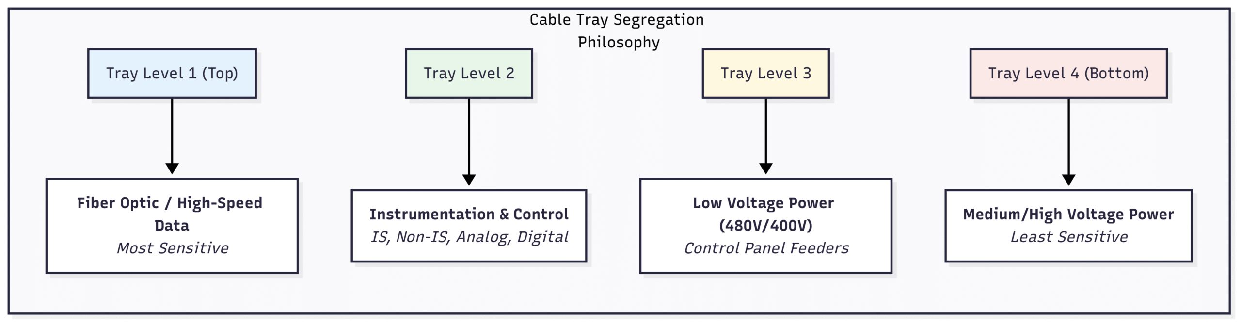
Segregation: This is a fundamental safety and reliability requirement.
Are power cables and instrument/control cables run in separate trays? A minimum separation distance (e.g., mm) is typically required.
Are Intrinsically Safe (IS) cables segregated from Non-IS cables?
Are fiber optic cables routed separately and protected from crushing?
Routing Path:
Do cable trays avoid “drip paths” under process piping flanges or equipment that might leak?
Are trays routed away from hot surfaces ($\> 60^\\circ C$)?
Do the routes provide the shortest practical path without obstructing maintenance access or walkways?
Support & Protection:
Are the cable tray supports adequate for the calculated weight of the cables?
Are trays covered in areas with a risk of falling objects or heavy UV exposure?
Are drop-outs from the tray to individual instruments done via protective conduit?
Junction Boxes (JBs):
Are JBs located in accessible locations (not behind pipes or vessels)?
Are they mounted at a convenient working height (typically meters from the platform)?
Is the JB protected from physical damage by vehicles or personnel?
Finalizing the Review: The Punch List
The output of a model review is not just a feeling of confidence; it’s a tangible, actionable list of comments known as a “punch list.”
Best Practices for Punch-listing:
Appoint a Scribe: Have one person dedicated to capturing comments in real-time.
Be Specific: A bad comment is “Valve access is poor.” A good comment is: “Control Valve LV-101 handwheel is blocked by pipe 4″-PL-1025. Rotate actuator 90 degrees clockwise to provide clearance.”
Use Screenshots: A picture is worth a thousand words. Include a snapshot from the 3D model with each comment.
Assign & Prioritize: Every comment must be assigned to a responsible discipline (e.g., Piping, I&C) and given a priority (e.g., Critical, Major, Minor).
Conclusion: Your Blueprint for Success
The 90% 3D model review is a high-stakes, high-value activity that pays dividends throughout the construction, commissioning, and operational life of a plant. By moving beyond simple clash detection and adopting a holistic review methodology that prioritizes safety, operability, and maintainability, you turn your digital model into a true blueprint for success.
Use these checklists to empower your team, challenge assumptions, and ensure that what you see in the model is exactly what you can build and operate safely and efficiently in the field. A thorough review today is the best insurance against a costly problem tomorrow.