Thermowell Installation Best Practice Codes: Ensuring Mechanical Integrity and Measurement Accuracy
1. Foundational Standards and Thermowell Classification
Thermowells are indispensable components in industrial process control, serving the dual and often conflicting roles of a process containment boundary and a temperature measurement interface. Due to their installation as cantilever beams directly into flowing fluid streams, they are subject to significant mechanical stresses in addition to static pressure and thermal loads. Consequently, their design and installation must adhere rigorously to established international engineering standards to prevent catastrophic failures.
1.1 The Crucial Role of Thermowells in Process Integrity and Measurement
The primary function of a thermowell is to provide mechanical and chemical protection for sensitive temperature sensors, such as Resistance Temperature Detectors (RTDs) or thermocouples, shielding them from hostile environments characterized by high pressures, corrosive media, abrasion, or high fluid velocities. Furthermore, the installation of a thermowell provides vital process isolation, enabling maintenance, calibration, or replacement of the sensor without necessitating a process shutdown or depressurization of the piping system. This capability significantly contributes to reducing operational downtime and increasing throughput.
1.2 Primary Governing Codes: ASME PTC 19.3 TW and ASME B31.3
The requirements governing thermowell design are segmented into two distinct, yet equally critical, categories: mechanical performance under flow conditions and structural integrity as a pressure vessel component.
1.2.1 ASME PTC 19.3 TW for Mechanical and Dynamic Analysis
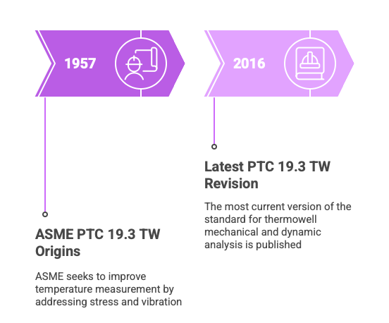
The definitive standard for evaluating the mechanical design and dynamic performance of a thermowell is ASME PTC 19.3 TW (Temperature Measurement Instruments and Apparatus), specifically the latest 2016 revision. This standard dictates the criteria for assessing stress effects and vibration avoidance, dating its origins to 1957 when ASME sought to improve upon earlier temperature measurement supplements that failed to account for these factors.
The scope of PTC 19.3 TW is specific: it applies only to thermowells machined from solid bar stock, including those welded or threaded into a flange or process vessel. This constraint is foundational, as the calculation methodologies within the standard rely on the geometric stability and consistent material properties inherent in bar stock construction to model the thermowell as a simple cantilever beam. Thermowells fabricated from pipe or tube material are explicitly excluded from this standard’s scope due to the variability and potential lack of concentricity inherent in multi-piece construction.
1.2.2 ASME B31.3 for Piping Integrity and Construction
The installation of a thermowell is intrinsically linked to piping system integrity. ASME B31.3 (Process Piping) governs the physical requirements for the attachment of the thermowell to the pipeline, covering fluid service definitions, welding procedures, and quality assurance. Related standards define the mechanical connections: ASME B16.5 specifies requirements for flanged fittings (e.g., raised face, ring joint), while ASME B16.11 covers socket-welded and threaded fittings.
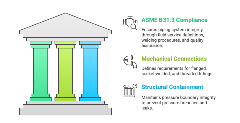
A successful thermowell installation requires mandatory compliance with both sets of codes. PTC 19.3 TW ensures the component survives the fluid forces (mechanical safety), while B31.3 ensures the component maintains the pressure boundary integrity of the piping system (structural containment). Failure to comply with PTC 19.3 TW risks fatigue-induced breakage; failure to comply with B31.3 risks a pressure breach or catastrophic leak.
1.2.3 Other Applicable Standards
International and industry-specific standards provide supplemental guidance. API Recommended Practice 551 (Process Measurement Instrumentation) historically addresses thermowell placement and immersion depth, often citing criteria, such as a 2 to 5 inch immersion depth, aligned with ASME practices. Furthermore, IEC 61520 specifies functional dimensions for metal thermowells used in process control applications.
2. Thermowell Mechanical Integrity: Stress and Vibration Analysis (ASME PTC 19.3 TW)
The single greatest threat to thermowell integrity is failure induced by fluid flow, known as Vortex-Induced Vibration (VIV). ASME PTC 19.3 TW provides the analytical framework necessary to predict and prevent such failures, requiring complex calculation methodologies to evaluate resonance potential and material stress limits.
2.1 Principles of Flow-Induced Vibration (VIV)
Thermowells are installed as a circular cylinder acting as a cantilever beam within the fluid stream. As the process fluid bypasses the thermowell, regions of low pressure—known as the Von Karman Vortex Street—are created downstream. This alternating formation of vortices generates dynamic transverse lift forces and static in-line drag forces. If the frequency of this vortex shedding (f_s) coincides with or approaches the thermowell’s natural frequency (f_n), a condition known as resonance occurs, leading to high-amplitude oscillations and rapid fatigue failure.
The wake frequency, f_s, is a function of the fluid velocity and the outer diameter of the thermowell. The natural frequency, f_n, is determined by the thermowell’s geometric properties (unsupported length, diameters) and the material’s mass density and modulus of elasticity.

2.2 The Four Quantitative Fitness-for-Service Criteria
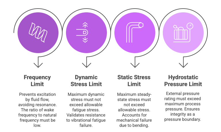
The ASME PTC 19.3 TW (2016) standard requires that a thermowell design meet four quantitative criteria to confirm its suitability for the intended operating conditions, ensuring longevity and mechanical safety.
2.2.1 Frequency Limit and Resonance Avoidance
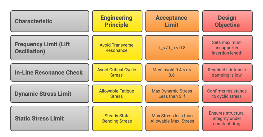
The primary safety criterion is designed to prevent excitation by the fluid flow. The ratio of the wake frequency to the natural frequency, r = f_s / f_n, must be sufficiently low. For general applications, the frequency ratio limit is r < 0.8 to avoid the high-amplitude, destructive transverse oscillation (main resonance) where r approx 1.
In specific low-damping environments (typically low-density gases), the analysis must also ensure the thermowell avoids the in-line resonance zone, which is triggered by drag oscillation and occurs when r approx 0.5. This translates to an exclusionary range of 0.4 < r < 0.6. The strict enforcement of this criteria protects the device against high-cycle fatigue.
2.2.2 Dynamic Stress Limit (Fatigue Check)
The maximum primary dynamic stress generated by the cyclic lift forces must not exceed the allowable fatigue stress limit (S_f) for the thermowell material at the operating temperature. For instance, the high-cycle limit S_f for welded carbon steel may be 3,000 psi. This calculation directly validates the thermowell’s resistance to vibrational fatigue failure over its expected service life.
2.2.3 Static Stress Limit
The static stresses imposed by the steady-state drag force from the fluid flow, combined with the external process pressure, must be managed. The maximum resulting steady-state stress, typically calculated using the Von Mises criteria, must not exceed the allowable stress of the material at the design temperature. This accounts for mechanical failure due to bending or yielding under normal operating conditions.
2.2.4 Hydrostatic Pressure Limit
The external pressure rating of the thermowell assembly—including the tip, shank, and process connection (flange or thread)—must demonstrably exceed the maximum expected process pressure. This criterion ensures the thermowell maintains its integrity as a pressure boundary component, independent of flow effects.
2.3 Scruton Number and Damping Exceptions
While the frequency ratio limit of r < 0.8 is generally mandatory, the modern PTC 19.3 TW standard incorporates a more nuanced approach through the utilization of the Scruton Number (N_{SC}). This dimensionless parameter quantifies the intrinsic damping factor, or vibration resistance capacity, of the thermowell and the surrounding fluid.
For fluid services, especially low-density gases, where N_{SC} is low (typically N_{SC} < 2.5), the intrinsic damping is insufficient, requiring strict adherence to resonance avoidance. However, as the Scruton Number increases—as often seen in high-density liquid processes—the damping level increases, mitigating the amplitude of deflection and stress at resonance. A sufficiently high N_{SC} may justify deeming the thermowell safe to operate even if the frequency ratio temporarily violates the r < 0.8 limit during startup or shutdown phases.
2.4 Engineering Solutions for VIV Mitigation
Design modifications are often necessary when a thermowell fails the frequency calculation:
Shortening the Insertion Length: Reducing the unsupported length (U-length) is the most effective technique recommended by ASME PTC 19.3 TW to increase the thermowell’s natural frequency, thereby lowering the frequency ratio r.
Tapered Profiles: Utilizing a tapered shank design, where the diameter decreases toward the tip, provides superior stiffness and better overall vibration resistance compared to straight or stepped profiles.
Vortex Suppression Devices: In extreme high-velocity applications where geometric adjustments are insufficient, incorporating helical strakes (e.g., ScrutonWell® design) physically disrupts the coherent formation of the Von Karman vortex street. This engineered approach can reduce oscillation amplitudes by over 90%, effectively eliminating VIV risk.
Table 2.1: ASME PTC 19.3 TW Fitness-for-Service Criteria Summary
3. Process Optimization and Installation Geometry
While mechanical integrity dictates the maximum size and shape, accurate measurement requires adherence to best practices regarding immersion depth and placement relative to fluid dynamics.
3.1 Immersion Length (U-Length) Determination for Optimal Accuracy
Proper immersion length is crucial for achieving rapid thermal equilibrium and ensuring the sensor measures the true process temperature, minimizing errors caused by heat being conducted away from the tip through the thermowell stem to the connection point (stem conduction error).
3.1.1 General Immersion Guidelines
The industry standard often employs a rule of thumb for placement within the pipe diameter: the thermowell tip should be inserted into the fluid stream anywhere from one-third (1/3) to two-thirds (2/3) of the way across the pipe, aiming for the middle third where temperature profiles are most stable in turbulent flow conditions. For minimum length requirements, guidelines recommend that the unsupported length (U-length) be at least 10 times the thermowell tip diameter, or a minimum of 2 to 5 inches (50 to 125 mm) into the process media.
3.1.2 Sensor Fit and Thermal Contact
To maximize measurement accuracy, the temperature sensor’s sensing element must be optimally located within the thermowell bore. Best practice dictates that the thermowell’s bored depth (referred to as the “S” length) must be 1 to 2 inches longer than the sensor probe to position the sensor correctly near the tip. Furthermore, to improve the heat transfer rate and minimize response time, spring-loaded sensors should be utilized, along with the application of a high-temperature heat transfer medium or paste within the bore.
3.2 Thermowell Orientation and Flow Profile Management
Optimizing Thermowell Orientation for Performance and Flow
In the complex world of process instrumentation, achieving accurate and reliable temperature measurement is paramount. While the temperature sensor itself (thermocouple or RTD) is the star of the show, its protective fitting—the thermowell—plays a critical, often-overlooked supporting role. Improper thermowell installation can lead to sluggish readings, measurement errors, and, catastrophically, mechanical failure due to flow-induced vibration. This blog delves into the engineering logic behind optimal thermowell orientation, focusing on how strategic placement directly impacts performance and crucial flow profile management.
The Thermowell’s Dual Challenge: Protection and Responsiveness
A thermowell is essentially a tubular fitting, closed at one end, designed to shield the delicate temperature sensor from the harsh realities of the process environment—high pressure, velocity, and corrosive media. It also allows for sensor replacement or calibration without shutting down or depressurizing the system.
However, the thermowell introduces an inherent challenge: it adds thermal mass between the fluid and the sensor, increasing the thermal lag or response time. Moreover, as a bluff body inserted into the flow, it is susceptible to dynamic forces, most notably vortex shedding.
The Flow-Induced Vibration (Vortex Shedding) Threat
When process fluid flows around the cylindrical thermowell, alternating low-pressure vortices—known as a Von Karman Vortex Street—are created on the downstream side . This phenomenon generates alternating transverse forces on the thermowell. If the frequency of this vortex shedding (the wake frequency) aligns with the thermowell’s natural frequency, resonance occurs. Resonance causes destructive, high-amplitude vibrations that lead to rapid fatigue and catastrophic failure, posing a serious safety risk. The ASME PTC 19.3 TW standard provides the methodology for calculating the wake frequency and ensuring the thermowell’s natural frequency is sufficiently higher (often requiring a safety factor of 2.2 or more) to prevent resonance.
Strategic Orientation: Beyond the 90° Standard
While a straight-in, 90° (perpendicular) installation is common, it is often not the optimal choice, especially in high-velocity applications. The process of mitigating vibration and improving thermal response hinges on strategic orientation.
The 45° Angled Installation: A Smart Engineering Choice
Installing the thermowell at a 45° angle relative to the direction of fluid flow offers several significant engineering advantages:
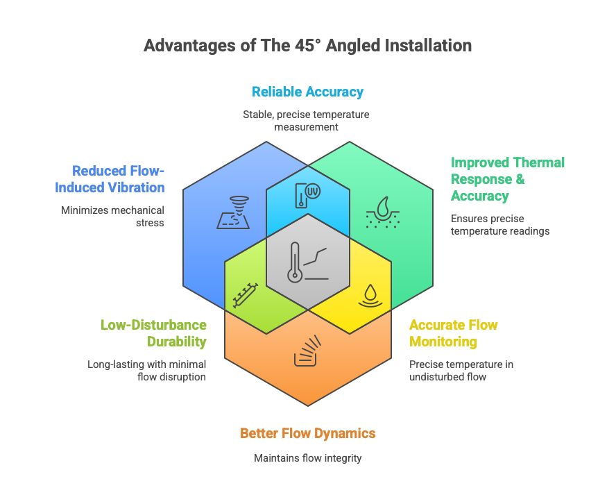
Reduced Flow-Induced Vibration: The 45° angle effectively lowers the cross-flow velocity component experienced by the thermowell. This reduction in the component of flow perpendicular to the well’s axis dramatically decreases the intensity of vortex shedding and lowers the resulting wake frequency. By lowering the wake frequency, the mechanical stress is reduced, increasing the service life and durability of the thermowell.
Improved Thermal Response and Accuracy: Angled installation allows for a longer effective immersion length(U-length) in the process stream within the same pipe diameter compared to a perpendicular installation. Greater immersion ensures that the sensitive tip of the temperature sensor is more fully exposed to the representative fluid temperature, minimizing conduction error (heat loss along the well to the cooler ambient environment). This translates to faster heat transfer, reduced thermal lag, and more accurate temperature readings.
Better Flow Dynamics: Angling the thermowell creates a less obstructive, more streamlined profile, leading to a lower pressure drop across the thermowell assembly. This helps maintain the integrity of the flow profile, which is particularly crucial in flow-sensitive applications like custody transfer, where minimal turbulence and energy loss are required.
Immersion Length and Sensor Placement
Regardless of the angle, the immersion length is paramount. Industry guidelines often suggest the thermowell tip should extend past the centerline of the pipe or, at minimum, be inserted between one-third and two-thirds of the way into the fluid stream. The sensor element inside the thermowell must also be fully immersed, with its tip making positive contact with the bottom of the thermowell’s bore (often ensured using a spring-loaded sensor) to minimize the insulating effect of any air gap.
Flow Profile Management: Location is Everything
The location of the thermowell in the piping system is just as vital as its orientation. The goal is to place the sensor in an area that offers a temperature measurement truly representative of the bulk fluid, away from disruptive flow patterns.
Avoiding Turbulence and Stratification
Avoid placement immediately downstream of fittings: Installations right after elbows, reducers, pumps, or control valves will encounter highly turbulent and often swirling flow profiles that can cause excessive vibration and inaccurate readings.
Optimal Straight Run: Place the thermowell in a straight run of pipe, ideally at a distance of 10 to 100 pipe diameters downstream of the nearest flow disturbance to ensure fully developed and more laminar flow. A conservative rule of thumb is often 25 pipe diameters.
Elbow Placement (Facing Upstream): In situations where straight-run space is limited, installing the thermowell in an elbow, facing upstream (into the flow), can be an effective way to get a centerline measurement. Conversely, facing the thermowell downstream in an elbow can lead to noisier, less representative readings due to swirling and separation.
Horizontal vs. Vertical Lines: In horizontal pipe runs, avoid placing the thermowell at the very bottom, where settling particulates (slurries) or condensate (steam lines) can accumulate. In large vertical pipes or vessels with low flow rates, vertical orientation may be necessary to counter thermal stratification (layers of different temperatures).
Thermowell Shank Profile: Tapered for Tough Flows
The geometry of the thermowell itself significantly influences its vibration resistance and response time:
Straight Shank: Constant diameter; highest mass, slowest response, typically for lower-velocity applications.
Stepped Shank: Reduced diameter at the tip; faster response due to less mass at the end, but the abrupt change in geometry can sometimes complicate vibration analysis.
Tapered Shank: Diameter gradually decreases from the root to the tip. This is the preferred profile for high-velocity flows, as it effectively balances mechanical strength, vibration resistance, and thermal response by reducing the tip’s mass while maintaining a robust connection root.
Optimal thermowell orientation and installation are not a matter of guesswork but a critical engineering discipline governed by industry standards like ASME PTC 19.3 TW. The choice to use a perpendicular or an angled installation, such as the widely preferred 45° orientation, must be a calculated one, based on a comprehensive understanding of the process fluid’s velocity, density, and the need to manage destructive flow-induced vibration. By strategically selecting the correct shank profile, ensuring adequate immersion, and optimizing the orientation—especially the vibration-mitigating 45° angle—engineers can guarantee that temperature measurement is not only accurate and fast but also safe and mechanically reliable for the long term.
The placement and orientation of the thermowell significantly impact both measurement accuracy and mechanical lifespan, particularly in relation to flow characteristics.
4. Material Selection, Compatibility, and Corrosion Codes
The selection of thermowell material is a critical design step that addresses chemical resistance, pressure rating, and mechanical strength requirements, all of which are interrelated through codified limits.
4.1 Selection Based on Process Conditions and Mechanical Stress
The thermowell material must possess the mechanical strength required to meet the static and dynamic stress limits calculated under ASME PTC 19.3 TW, while simultaneously resisting chemical degradation from the process fluid. Common materials include 316 Stainless Steel for good corrosion resistance in chemical processing and food/beverage industries, and higher-strength alloys like Chrome/Moly Steels (F11, F22) for high-pressure industrial boiler applications. Exotic alloys such as Monel, Inconel, and Hastelloy are specified for extremely high temperatures or aggressive corrosive services.
A key requirement for pressure containment is that the thermowell’s connection to the piping system must be rated adequately. For flanged thermowells, the flange material should ideally match the stem material to prevent potential galvanic corrosion. The pressure rating of the flange (e.g., 150 lbs through 2,500 lbs) must conform to ASME B16.5 standards and is often the limiting factor for the maximum allowable pressure of the entire assembly.
4.2 Compliance for Sour Service (NACE MR0175 / ISO 15156)
For applications involving hydrogen sulfide (H_2S), known as sour service, material selection must strictly comply with NACE MR0175 / ISO 15156. This standard provides requirements and recommendations for metallic materials to mitigate the risk of Sulfide Stress Cracking (SSC), which can lead to premature failure in H_2S-containing environments.
Compliance necessitates tight control over material hardness. Post Weld Heat Treatment (PWHT) is often required for welded connections in sour service to reduce the hardness in the Heat Affected Zone (HAZ) and relieve residual stresses, both of which reduce the susceptibility to SSC. The use of compliant materials, such as specific grades of 316 SS, 6 Moly alloys, and Alloy 400, is necessary. Certification for NACE MR0175 compliance is a mandatory documentation requirement for such installations.
4.3 Material Verification and Traceability
To ensure the integrity of mechanical calculations, particularly the dynamic stress limits which rely on specific material properties (density, fatigue endurance limit), complete material traceability is necessary. Best practice requires the procurement of Certified Material Test Reports (MTRs, such as EN10204 3.1) from the vendor.
Furthermore, Positive Material Identification (PMI) testing, often performed using X-Ray Fluorescence Spectrometry (ASTM E572), is critical, especially for alloy thermowells and welds in critical service. Relying solely on general material data for calculation is discouraged, as specific material batches may not align with the assumed properties, potentially compromising the integrity of the PTC 19.3 TW analysis. Therefore, confirming the actual material composition through PMI ensures the installed component matches the design basis.
5. Fabrication, Quality Control (QA/QC), and Piping Code Integration (ASME B31.3)
The installation’s final integrity is verified through stringent quality control measures, including non-destructive testing (NDT) and mandatory pressure boundary certification protocols dictated by ASME B31.3.
5.1 Construction Requirements and Tolerances
Thermowells used in industrial processes are typically machined from solid bar stock to ensure structural consistency and high pressure integrity. Tight manufacturing tolerances are applied to critical dimensions. For instance, bore depth (“S” length) tolerances are stringent (e.g., pm 0.020 inches), and bore diameter must be closely controlled (e.g., +0.005 inches / -0.003 inches for standard bore sizes) to guarantee optimal sensor fit and response time.
Process connections include flanged, threaded (NPT), socket-welded, and sanitary types (Tri-Clamp). For welded connections, such as flanged thermowells, double-welded construction is often employed, using a primary groove weld and a secondary bevel groove weld, which eliminates crevices susceptible to corrosion.
5.2 Mandatory Pressure Testing and Verification
Thermowells, as pressure containment components, must undergo thorough pressure testing before installation.
5.2.1 Hydrostatic Testing
Hydrostatic testing is a mandatory step specified by ASME B31.3 for all pressure piping components, including thermowells. The test typically requires loading the thermowell with water (preferably with a low chloride content, $< 15$ ppm, to avoid chloride stress corrosion) to a test pressure equal to $1.5$ times the nominal design pressure, and maintaining this pressure for a specified duration (e.g., 10 minutes). Successful completion of this test is documented via an ASTM E1003 compliant certificate and often requires physical marking of the thermowell with a designation such as “P”.
5.2.2 Non-Destructive Examination (NDE/NDT) Procedures
The extent of NDT is driven by the fluid service category and design specifications. Key NDT methods include:
Visual Examination (VT): A mandatory requirement for 100% of all completed welds and a baseline QA/QC procedure.
Liquid Penetrant Inspection (LPI): Used to detect surface-breaking defects in welds, commonly applied to all weld seams.
Radiography (RT) and Ultrasonic Testing (UT): Used for examining the internal volume and soundness of full penetration welds, such as those required for high-pressure flanged or weld-in installations. ASME B31.3 sets protocols for progressive sampling if defects are detected.
Positive Material Identification (PMI) and Hardness Testing (HT): Mandatory for critical and sour services to ensure material composition and hardness requirements (NACE compliance) are met.
5.3 Post Weld Heat Treatment (PWHT) Requirements
PWHT is a crucial step for certain materials, such as alloy steels and carbon steels, to reduce internal residual stresses and temper the weld zone. ASME B31.3 mandates PWHT based on material P-number (material grade) and thickness, defining minimum holding temperature ranges and times.
However, B31.3 provides specific exemptions for small attachments like fillet or socket welds, often contingent on the throat thickness being less than 1/2 inch and the pipe material carbon content being < 0.15%. Despite these exemptions, if the thermowell is destined for NACE MR0175 sour service, PWHT may become mandatory regardless of thickness exemptions to achieve the necessary hardness reduction for SSC resistance.
Table 5.1: Minimum Quality Assurance Requirements for Thermowell Compliance
| Verification Activity | Governing Code | Scope and Rationale | Mandatory Compliance |
| Wake Frequency Calculation Report | ASME PTC 19.3 TW | Confirms structural stability against VIV failure. | Mandatory for all flowing media. |
| Hydrostatic Testing Certificate | ASME B31.3 / ASTM E1003 | Verifies pressure boundary integrity (1.5 times design pressure). | Mandatory. |
| Visual Examination (VT) | ASME B31.3 | 100% inspection of completed welds. | Mandatory. |
| Positive Material ID (PMI) | Project/NACE Specifications | Ensures installed material matches calculated material properties. | Mandatory for critical/sour service. |
| Material Test Reports (MTRs) | EN10204 3.1 | Traceability of raw material composition and properties. | Mandatory. |
6. Conclusions and Best Practice Recommendations
The successful design and installation of a thermowell hinge upon the rigorous application of engineering codes, primarily centered on mechanical integrity and containment safety. The complexity of thermowell installation demands an integrated approach that balances thermal measurement requirements against dynamic stress limitations.
6.1 Priority of Mechanical Integrity over Measurement Accuracy
The most critical finding is the absolute necessity of complying with the ASME PTC 19.3 TW criteria to prevent VIV-induced fatigue failure. This requirement often forces a compromise on the desired unsupported insertion length (U-length), which might optimally extend into the pipe center (middle third) for perfect accuracy.
A recurring design scenario involves pressure to maximize insertion length for marginally better accuracy. However, pushing the frequency ratio close to the r=0.8 limit for small gains in thermal response significantly increases the risk profile. The catastrophic consequences of thermowell breakage—including depressurization, material loss, and potential injury—far outweigh the benefits of a slightly more accurate reading. Therefore, best practice dictates that mechanical safety criteria must always supersede minor optimization goals for thermal accuracy.
6.2 Integrated Design Strategy
Instrumentation design specialists must adopt an integrated strategy encompassing the following:
Mandatory Certification: Every thermowell destined for fluid service must be accompanied by a certified Wake Frequency Calculation report based on ASME PTC 19.3 TW.
Vibration Mitigation: Employ standard mitigation techniques, prioritizing shortening the U-length and utilizing tapered profiles. If high velocity persists, specify advanced solutions such as helical strakes.
Process Connection Integrity: Ensure all process connections—flanged, threaded, or welded—comply with ASME B31.3 and relevant B16 codes, and mandate the required NDT (LPI, RT, UT) based on fluid service and weld quality.
Sour Service Protocol: For H₂S service, compliance with NACE MR0175 is non-negotiable, requiring specific material selection, certified MTRs, PMI, and confirmation of PWHT protocols to manage hardness.
By strictly adhering to these codified best practices, engineers ensure the installed thermowell functions effectively as a stable sensor interface while maintaining the integrity and safety of the pressure containment system.