
Top 10 Thermocouple Troubleshooting Tips for Field Engineers
Thermocouples are the workhorses of temperature measurement in countless industrial applications. From massive furnaces to sensitive chemical reactors, these simple, robust sensors provide critical data for process control and safety. However, when a temperature reading goes awry, the humble thermocouple is often the first component to be blamed. As a field engineer, being able to quickly and accurately diagnose thermocouple issues can save significant time, money, and prevent unnecessary downtime.
This guide provides a comprehensive, in-depth look at the top 10 thermocouple troubleshooting tips, designed specifically for engineers and technicians on the ground. We’ll move from basic visual checks to more advanced diagnostic techniques, providing practical steps, theoretical background, and helpful diagrams to make you a troubleshooting expert.
1. Start with a Thorough Visual Inspection
Before you break out any test equipment, always start with a careful visual inspection of the entire thermocouple circuit. It’s the simplest step, yet it can often reveal the root cause of the problem immediately. You’re looking for any signs of physical distress or environmental damage.
What to Look For:
At the Sensor Tip (Hot Junction): Check the thermocouple sheath for signs of corrosion, erosion, or mechanical damage. In high-temperature or chemically aggressive environments, the sheath can become brittle, cracked, or even eaten away. A compromised sheath can lead to contamination of the thermocouple wires and cause rapid failure. Look for discoloration, which might indicate extreme over-temperature conditions.
Along the Cable/Extension Wire: Walk the entire length of the thermocouple wire and its extension cable. Look for frayed insulation, cuts, kinks, or areas where the cable has been crushed. Pay close attention to cable trays where heavy power cables might be resting on the sensitive signal wire. Check for exposure to excessive heat, moisture, or chemicals that could degrade the insulation and lead to shorts.
At the Connection Head/Terminals: Open the thermocouple connection head. Look for loose terminals, signs of corrosion on the screws or wires (often appearing as a white or green powder), and evidence of moisture ingress. A loose connection is one of the most common causes of erratic or open-circuit readings.
The Workflow: A Visual Checklist
Here is a simple workflow to follow for your visual inspection.
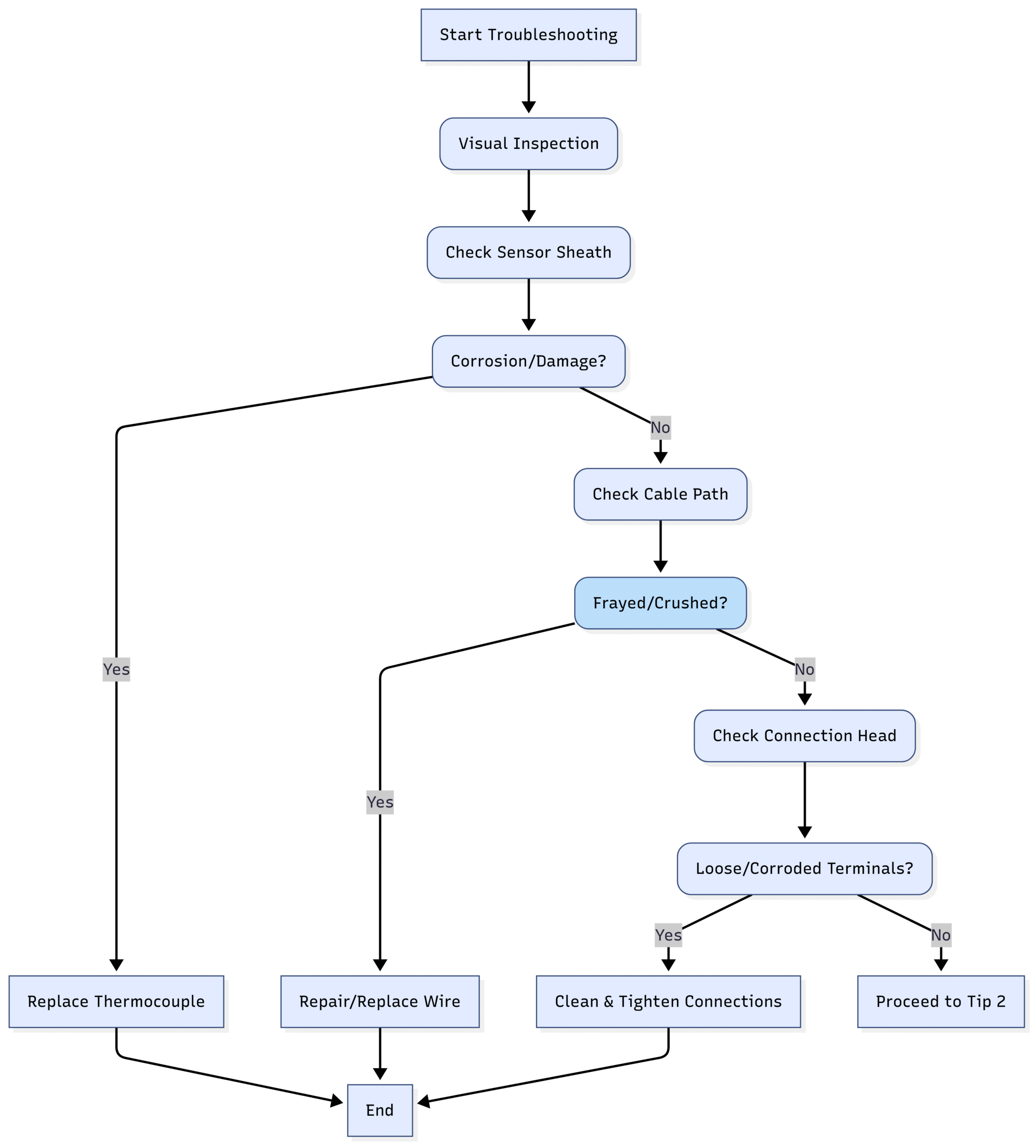
A systematic visual check establishes a baseline and often prevents you from wasting time on more complex troubleshooting steps.2. Verify All Connection Points are Secure and Correct
A thermocouple circuit is only as strong as its weakest link, and that weak link is often a connection point. The low-level millivolt () signal generated by a thermocouple is highly susceptible to interference from poor connections.
Key Connection Points to Scrutinize:
Thermocouple to Connection Head: This is the terminal block inside the sensor’s head where the thermocouple wires connect. Ensure these screws are tight.
Connection Head to Extension Wire: Where the field cable connects to the thermocouple head. Again, check for tightness and corrosion.
Extension Wire to Instrument (PLC/DCS/Transmitter): This is the final destination. These terminals are often in a crowded cabinet. Double-check that you’re looking at the correct input and that the connections are secure.
A loose connection can create a variable resistance, causing the temperature reading to fluctuate wildly or read intermittently. Corrosion acts as an insulator, which can lead to an open circuit fault or a significantly attenuated signal.
The Complete Circuit Diagram
Understanding the entire signal path helps you systematically check each point.
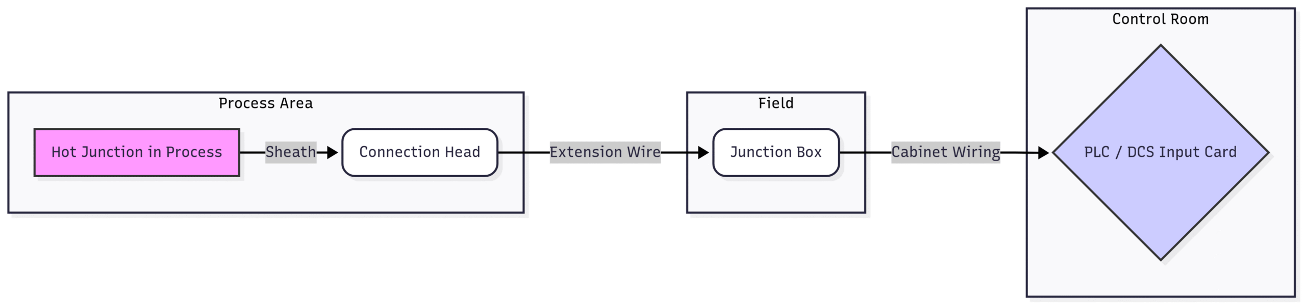
When checking connections, don't just look—gently tug on the wires to ensure they are mechanically secure in the terminal. Use a contact cleaner if you see any signs of oxidation, and always re-tighten to the manufacturer's specification.3. Confirm Correct Polarity Throughout the Circuit
This is a classic and surprisingly common mistake. A thermocouple works by joining two dissimilar metals. Reversing these metals anywhere in the circuit will lead to significant measurement errors. Each leg of a thermocouple has a positive (+) and a negative (-) wire, and this polarity must be maintained from the sensor all the way to the measuring instrument.
How Reversed Polarity Affects Readings:
According to the Seebeck effect, the voltage generated is proportional to the temperature difference between the hot junction and the cold junction: . If you reverse the polarity, you essentially measure .
Result: The instrument will read a temperature that decreases as the process temperature increases. Often, the reading will be close to ambient temperature and then drop as the process heats up.
Checking Polarity: Color Codes
Manufacturers use color codes to identify the positive and negative legs. Crucially, these codes vary by country and thermocouple type. Always have a reference chart handy. For example, in the US (ANSI standard):
Type K: Yellow (+) / Red (-)
Type J: White (+) / Red (-)
Type T: Blue (+) / Red (-)
Type E: Purple (+) / Red (-)
The negative leg is almost always red in the ANSI system.
Diagram: Correct vs. Reversed Polarity
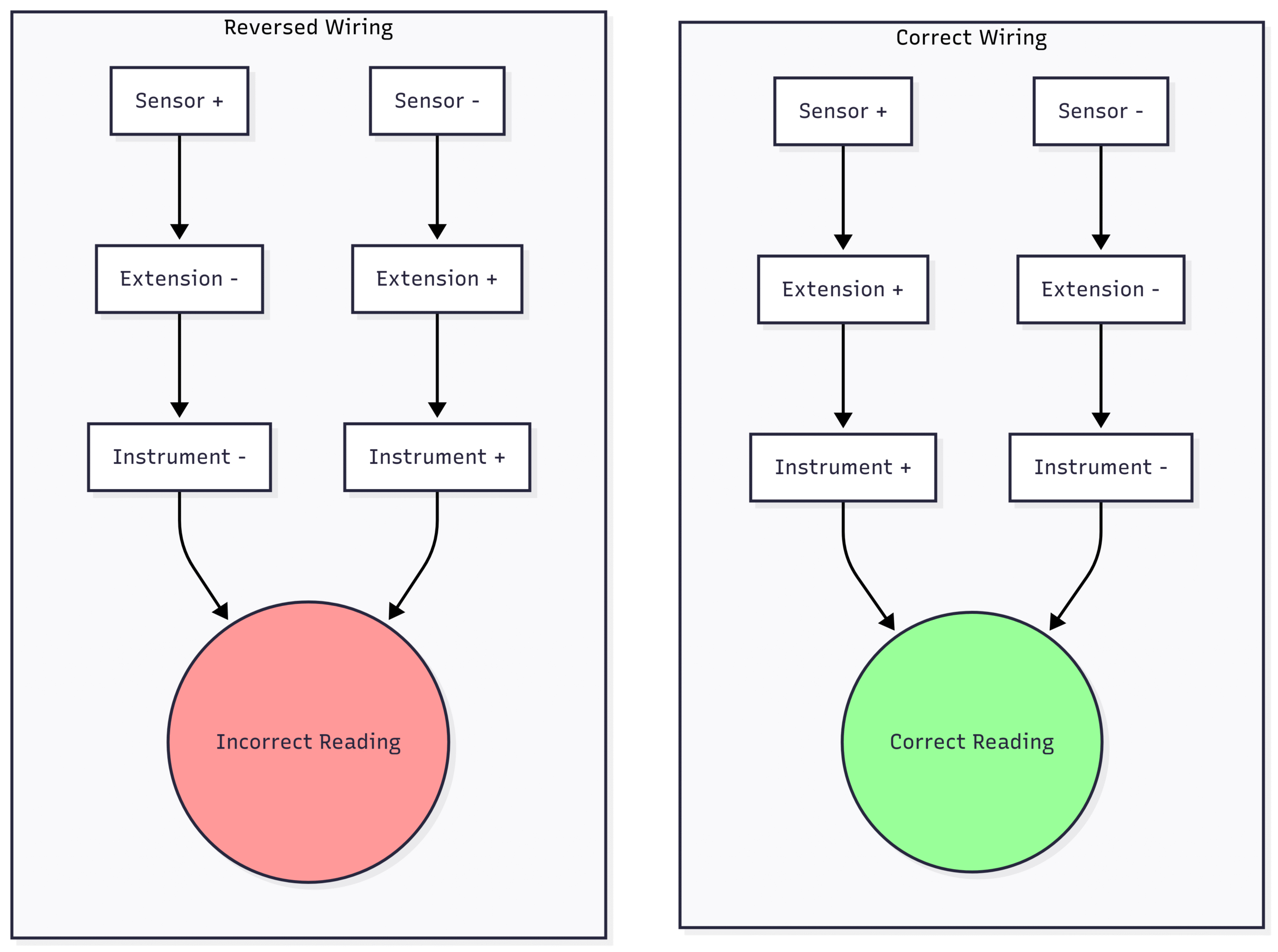
Trace the wiring from end to end. Verify that the positive wire from the thermocouple connects to the positive terminal on the extension wire, which then connects to the positive terminal on the instrument. Repeat for the negative side.4. Isolate and Test the Thermocouple Independently
If the visual checks and polarity verification don’t solve the problem, it’s time to determine if the sensor itself has failed. The best way to do this is to isolate it from the rest of the circuit and test its output directly.
The Test Procedure:
Disconnect: Go to the thermocouple connection head and disconnect the extension wire, completely isolating the thermocouple.
Connect Multimeter: Set a quality digital multimeter (DMM) to the DC millivolts () range. Connect the DMM’s positive lead to the thermocouple’s positive terminal and the negative lead to the negative terminal.
Measure Ambient Temperature: The thermocouple’s hot junction is currently at the ambient temperature of its location. You should see a small reading on your DMM.
Compare to a Chart: Use a thermocouple reference table (easily found online or in engineering handbooks) for the specific TC type you’re testing. Find the current ambient temperature and see what the corresponding output should be. For example, a Type K thermocouple at 25 °C (77 °F) should generate approximately . If your reading is close to this, it’s a good sign.
Apply Heat (Optional & Careful): If safe to do so, you can gently heat the tip of the thermocouple with a heat gun or even by holding it in your hand. You should see the reading climb steadily. This confirms the thermocouple is responding to temperature changes. CAUTION: Never use an open flame unless you are certain the atmosphere is not flammable.
Workflow for Independent Testing
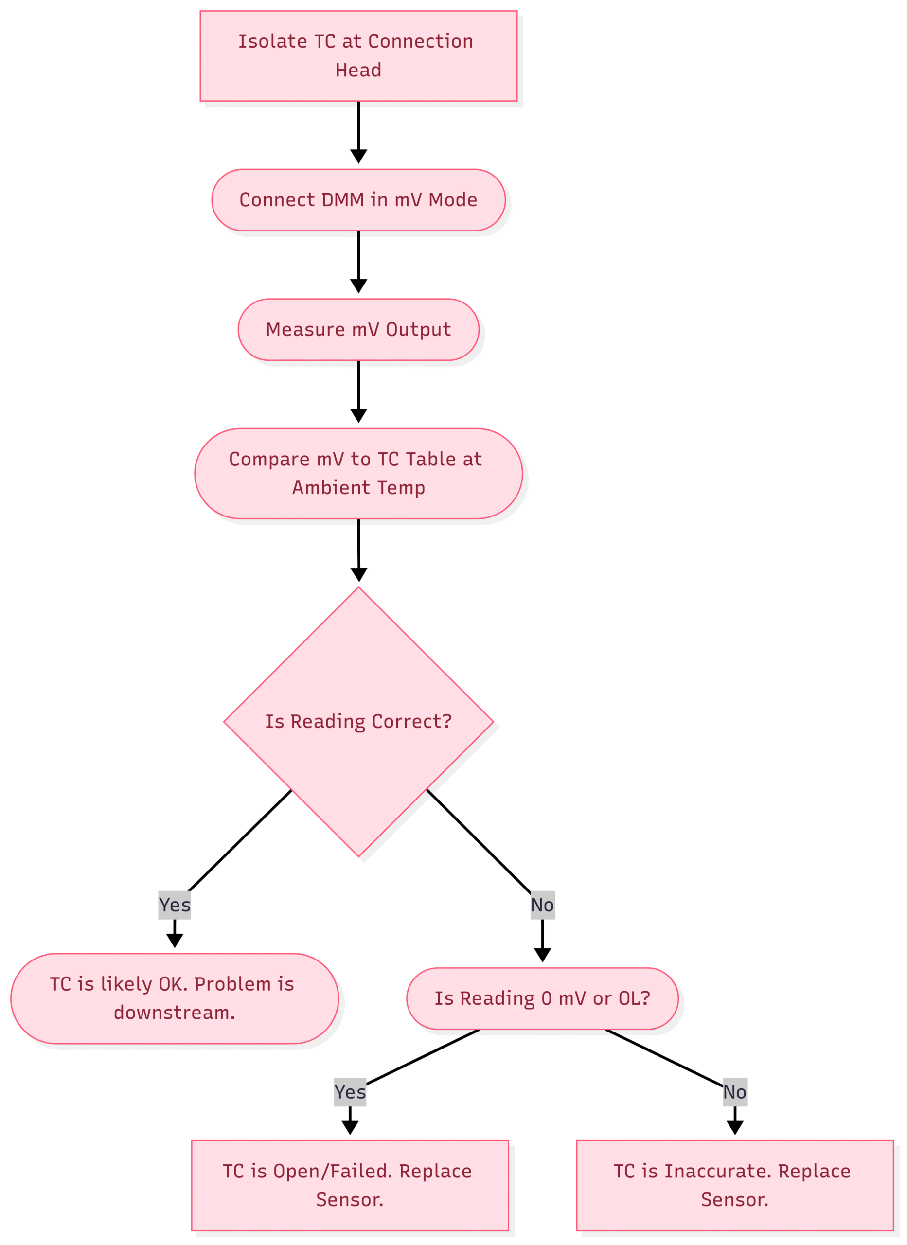
This test definitively proves whether the sensor itself is functional or has failed. If it passes this test, the problem lies in the extension wire or the measuring instrument.5. Scrutinize the Thermocouple Extension Wire
The extension wire is not just a regular electrical cable; it’s a critical component of the measurement circuit. It must be made of materials with the same thermoelectric properties as the thermocouple itself. Using the wrong type of wire is a very common source of error.
Common Extension Wire Problems:
Wrong Material: If an electrician installs standard copper wire instead of the proper thermocouple extension wire, they create a new thermocouple junction at the connection head. The instrument will then measure the temperature at the head, not at the process.
Short Circuits: Insulation failure can cause the positive and negative wires to touch. This moves the effective “hot junction” to the location of the short, meaning you’ll be reading the temperature wherever the short has occurred along the cable path.
Continuity/Open Circuit: A break in one or both conductors will result in an “open” or “off-scale high” reading on most instruments.
How to Test the Extension Wire:
Disconnect at Both Ends: Disconnect the wire from the thermocouple head and the measuring instrument.
Continuity Check: Use a DMM in resistance () mode. At one end, short the positive and negative wires together. Go to the other end and measure the resistance between the positive and negative wires. You should read a low resistance, representing the loop resistance of the cable (typically a few ohms). An “OL” (Over Limit) reading indicates a break in the wire.
Short Circuit Check: With the wires un-shorted at the far end, measure the resistance between the positive and negative conductors. It should read “OL,” indicating they are not touching. Any finite resistance reading indicates a short.
Ground Fault Check: Measure the resistance from each conductor to ground (e.g., the cable shield or a nearby conduit). This should also read “OL.”
This systematic check will confirm the integrity of the cable connecting your sensor to your control system.
6. Validate the Measuring Instrument (Input Card)
If you’ve confirmed the thermocouple and extension wire are both good, the problem may lie with the instrumentation itself—the PLC input card, DCS, temperature transmitter, or panel meter. The easiest way to verify the instrument’s function is to feed it a known signal.
Using a Thermocouple Simulator/Calibrator:
A thermocouple simulator, or a multi-function process calibrator, is an essential tool for any instrumentation professional. It can generate a precise signal that corresponds to a specific temperature for any TC type.
The Procedure:
Disconnect Extension Wire: At the instrument’s input terminals, disconnect the extension wire coming from the field.
Connect Simulator: Connect the output leads of your simulator directly to the instrument’s input terminals. Ensure the polarity is correct (+ to +, – to -).
Configure Simulator: Set your simulator to the correct thermocouple type (e.g., Type K).
Send Known Signals:
Start by simulating a 0 °C or ambient temperature signal. The instrument display should match this value.
Simulate a value at 25%, 50%, 75%, and 100% of the instrument’s typical operating range. For example, if the process runs at 400 °C, test at 100 °C, 200 °C, 300 °C, and 400 °C.
Check for Linearity: The instrument’s readings should closely match the values you are simulating across the entire range. If they match, your instrument is working correctly. If they are off, non-linear, or don’t respond, the input card is faulty and needs to be reconfigured or replaced.
Test Setup Diagram
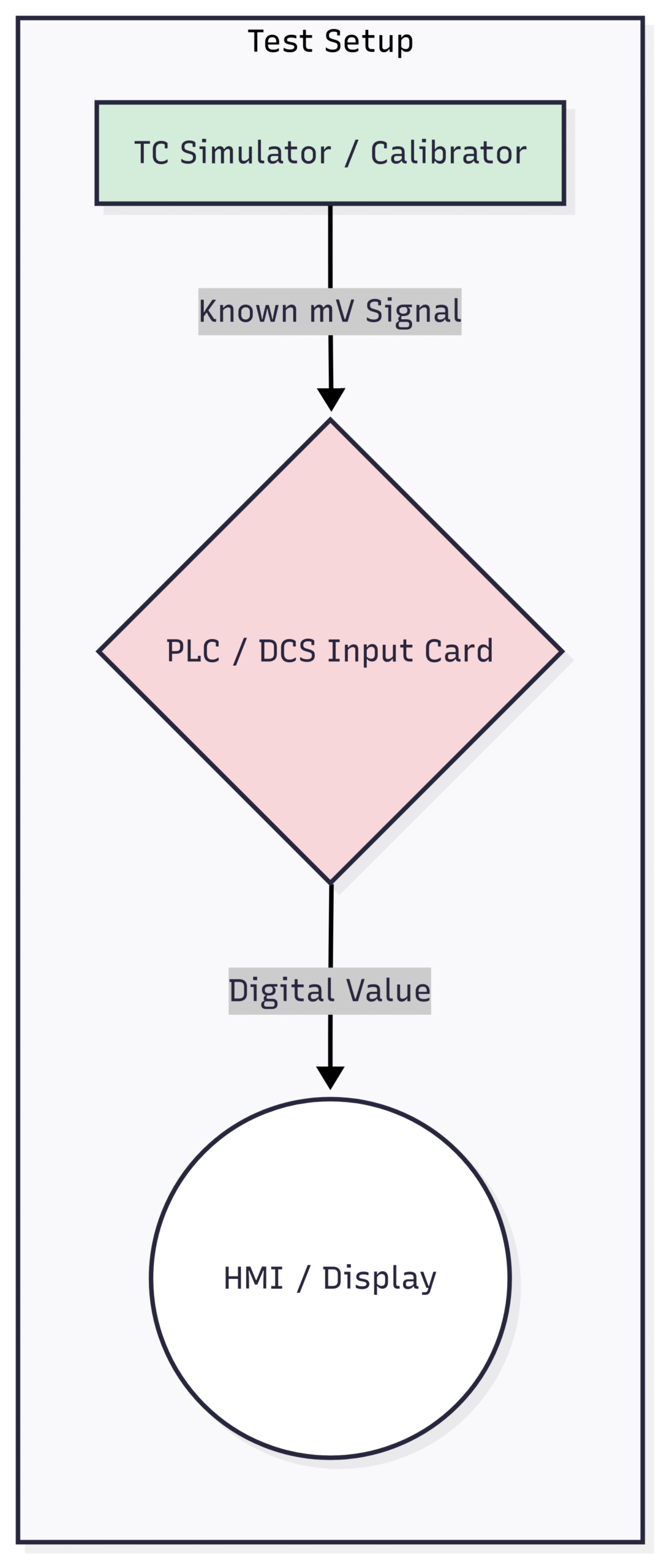
This test completely removes the field sensor and wiring from the equation, allowing you to focus solely on the control system hardware.7. Understand and Check Cold Junction Compensation (CJC)
This is a more advanced but absolutely critical concept. A thermocouple only measures a temperature difference between its hot end and its “cold” end (where it connects to the instrument). To get an absolute temperature reading, the instrument must know the temperature of that cold junction and add it to the measured difference. This is called Cold Junction Compensation (CJC).
The CJC is usually a small, precise temperature sensor (like a thermistor or RTD) located directly on the terminal block of the PLC/DCS input card where the thermocouple wire lands.
How CJC Failure Causes Errors:
Failed CJC Sensor: If the CJC sensor fails, the instrument might default to a fixed value (e.g., 0 C or 25 C) or read a nonsensical value.
Inaccurate CJC: If the CJC sensor is inaccurate, its error will be added directly to every single temperature reading. For example, if the CJC is reading 5 °C too high, all your process readings will be 5 °C too high.
Poor Thermal Contact: If the CJC sensor is not in good thermal contact with the terminal block, or if there’s a strong heat source nearby (like a power supply in the cabinet), it won’t accurately reflect the temperature of the thermocouple connections.
Troubleshooting CJC:
Locate the CJC: Find the CJC sensor on the input card’s terminal strip.
Compare to Ambient: Measure the actual temperature inside the cabinet near the terminal block with a reliable thermometer (like an IR gun or a separate test thermometer).
Check in Software: In the PLC/DCS configuration software, there is usually a diagnostic tag that shows the measured CJC temperature. Compare this value to your physical measurement. They should be within a degree or two of each other. If there’s a large discrepancy, the CJC sensor or the input card may be faulty.
8. Guard Against Electrical Noise (EMI/RFI)
The signal from a thermocouple is a very low-level analog signal, making it extremely vulnerable to corruption from electrical noise, also known as Electromagnetic Interference (EMI) or Radio Frequency Interference (RFI).
Common Sources of Noise:
AC Power Cables: Running thermocouple wires parallel to high-voltage power cables is a primary source of 60/50 Hz induced noise.
Variable Frequency Drives (VFDs): VFDs that control large motors generate a massive amount of electrical noise across a wide frequency spectrum.
Contactors, Relays, and Solenoids: The switching of inductive loads creates voltage spikes and noise.
Radio Transmitters: Two-way radios used by plant personnel can induce noise if used too close to sensitive wiring.
Best Practices for Noise Immunity:
Use Shielded, Twisted-Pair Extension Wire: This is the single most effective defense. The twisting cancels out magnetic field interference, and the shield, when properly grounded at one end only (typically the instrument end), drains away electrostatic noise.
Maintain Separation: Route thermocouple cables in separate conduits or trays from power cables. If they must cross, ensure they cross at a 90-degree angle to minimize inductive coupling.
Proper Grounding: Ground the shield of the extension wire to the instrument’s ground. Never leave it floating and avoid grounding it at both ends, as this can create a ground loop (see Tip 9).
9. Identify and Eliminate Ground Loops
A ground loop is a subtle but troublesome issue that occurs when there are multiple ground paths for a single circuit. This is particularly problematic for grounded thermocouples, where the tip of the thermocouple sheath is welded to the measuring junction, putting it in electrical contact with the process vessel (which is usually grounded).
If the instrument at the other end is also grounded, you create a loop. Any difference in ground potential between the process vessel and the control cabinet will cause a small current to flow through the thermocouple wire. This current interferes with the tiny signal, causing significant errors.
How to Diagnose and Fix Ground Loops:
Identify TC Type: First, determine if you have a grounded or ungrounded thermocouple. An ungrounded TC’s junction is electrically isolated from the sheath and is generally immune to ground loops.
Lift the Ground: If you have a grounded thermocouple and suspect a ground loop, a quick diagnostic is to temporarily lift the ground at the instrument end. You can do this by disconnecting the shield drain wire. If the reading becomes stable and accurate, you’ve found a ground loop.
Use a Signal Isolator: The proper, permanent solution is not to leave the shield ungrounded. Instead, install a signal isolator. This device uses transformers or optical couplers to pass the signal through without a direct electrical connection, breaking the ground loop while maintaining safety and signal integrity.
Switch to Ungrounded TCs: For new installations or during replacements, always prefer ungrounded thermocouples unless a grounded junction is specifically required for faster response time.
10. Perform a Full-Loop Field Calibration Check
Finally, when you need to be absolutely certain of your measurement’s accuracy, the best method is a full-loop check using a known temperature source. This tests the thermocouple, extension wire, and instrument all together as a single system. The most common tools for this are a dry-block calibrator or, for a simple 0 °C check, an ice bath.
Using a Dry-Block Calibrator:
A dry-block is a portable furnace with a heated metal block containing wells to insert temperature probes.
Safety First: Ensure the process is in a safe state to have the thermocouple removed. Follow all Lock-Out/Tag-Out (LOTO) procedures.
Remove Sensor: Carefully remove the process thermocouple.
Insert Sensors: Place the process thermocouple into one well of the dry-block. Place a high-accuracy reference thermometer (often a certified RTD) into an adjacent well.
Heat to Setpoints: Set the dry-block to heat to a temperature near the low end of the process range. Allow it to stabilize completely.
Compare Readings: Compare the reading on your control system (from the process TC) to the reading from the high-accuracy reference thermometer. They should agree within an acceptable tolerance.
Repeat at Multiple Points: Repeat the test at mid-range and high-range process temperatures to check the system’s linearity and accuracy across its operating span.
The Ice Bath Method (for 0 °C / 32 °F):
An ice bath, made from a mixture of crushed ice and a small amount of water, provides a highly accurate and stable 0 °C reference point.
Prepare a proper ice bath in an insulated flask.
Remove the process TC and immerse its tip at least 3-4 inches into the ice bath.
Allow the reading to stabilize for several minutes.
The reading on your control system should be exactly 0 °C ( 32 °F). Any deviation is the total error of your measurement loop at that point.
This final check gives you ultimate confidence in your entire temperature measurement system, from the sensor tip to the operator’s screen.
Conclusion: A Systematic Approach is Key
Troubleshooting thermocouples doesn’t have to be a guessing game. By following a logical, systematic process—starting with the simplest checks and moving to more complex diagnostics—you can efficiently pinpoint the source of any problem. Always remember to work safely, document your findings, and use the right tools for the job. Mastering these ten tips will make you a more effective and valuable field engineer, capable of keeping critical processes running accurately and safely.