In the industrial processes, the control valve is a pivotal performer, regulating the flow of fluids and gases to ensure operational harmony. However, like any hardworking component, control valves are susceptible to failure. A malfunctioning valve can disrupt production, compromise safety, and lead to costly downtime. For engineers and technicians, understanding the common failure modes and knowing how to troubleshoot them effectively is a critical skill.
This comprehensive guide delves into the top seven control valve failures, exploring their symptoms, underlying causes, and the step-by-step procedures to diagnose and resolve them. We will also introduce clear diagrams to demystify complex concepts and empower you to keep your processes running smoothly.
1. The Unresponsive Valve
One of the most frequent issues plaguing control valves is “stiction,” a portmanteau of “static” and “friction.” This occurs when the valve’s moving parts, primarily the stem and packing, experience excessive friction, causing the valve to get stuck or move in a jerky, unpredictable manner.
Symptoms:
- Jerky or erratic valve movement: The valve does not respond smoothly to control signals.
- Process cycling: The process variable (e.g., temperature, pressure) oscillates around the setpoint because the valve overshoots its target position.
- Increased actuator pressure required: The actuator needs to apply more force than usual to move the valve.
- Positioner hunting: The valve positioner continuously adjusts, trying to find the correct position.
Potential Causes:
- Overtightened packing: The packing material, designed to prevent leaks along the valve stem, can be tightened excessively, creating a stranglehold on the stem.
- Galling or seizure of guiding surfaces: Metal-to-metal contact between the stem and guide bushings can lead to wear and seizure, especially at high temperatures.
- Process fluid buildup: Sticky or solidifying process fluids can accumulate on the stem and in the packing box, increasing friction.
- Corrosion: Corrosion on the valve stem or within the guide bushings creates a rough surface, impeding smooth movement.
- Bent stem: A bent valve stem will inevitably bind against the packing and guides.
Troubleshooting Steps:
- Visual Inspection: Begin by visually inspecting the valve stem for any signs of corrosion, damage, or process fluid residue.
- Check Actuator Air Supply: For pneumatic actuators, ensure the air supply pressure is within the manufacturer’s specified range. Insufficient pressure can mimic the symptoms of stiction.
- Loosen Packing Gland Nuts: Carefully and incrementally loosen the packing gland nuts while the valve is in operation (if safe to do so). Observe if this allows the valve to move more freely. Be prepared to retighten them slightly if a leak occurs.
- Stroke the Valve: Manually or through the control system, stroke the valve through its full range of motion. Feel for any rough spots or points of high resistance.
- Isolate and Inspect: If the problem persists, isolate the valve from the process, de-pressurize it, and remove the actuator. This allows you to manually move the stem and feel for binding.
- Disassemble and Clean: If binding is confirmed, disassemble the valve to inspect the stem, packing, and guide bushings. Clean all components thoroughly and replace any damaged parts. When reassembling, use the correct packing material and follow the manufacturer’s guidelines for tightening the packing gland.
2. Valve Leakage: The Unwanted Escape
Valve leakage can be categorized into two main types: external (fugitive emissions) and internal (passing). External leakage, where process fluid escapes to the atmosphere, is a serious safety and environmental concern. Internal leakage occurs when the valve does not shut off tightly, allowing fluid to pass through even when the valve is in the closed position.
Symptoms:
- External Leakage:
- Visible drips or streams of fluid from the valve body, bonnet, or packing gland.
- Audible hissing sound (for gases).
- Unpleasant odors.
- Stains or corrosion on the valve exterior.
- Internal Leakage:
- Inability to achieve a complete shutdown of the process flow.
- Process variable drifting from the setpoint when the valve is supposed to be closed.
- Temperature or pressure changes downstream of the closed valve.
Potential Causes:
- External Leakage:
- Worn or damaged packing: The most common cause of stem leakage.
- Damaged gaskets: Gaskets between the valve body and bonnet can degrade over time.
- Corrosion or cracks in the valve body or bonnet: Physical damage to the valve’s pressure-retaining components.
- Internal Leakage:
- Worn or damaged seat and plug (trim): Erosion, corrosion, or solid particles can damage the sealing surfaces.
- Incorrect valve stroking: The actuator may not be adjusted correctly to fully close the valve.
- Debris trapped between the seat and plug: Foreign material can prevent proper closure.
- High differential pressure: Excessive pressure drop across the valve can sometimes force fluid past the seals.
Troubleshooting Steps:
- Identify the Leak Source (External): For external leaks, carefully pinpoint the exact location of the leak (packing gland, bonnet gasket, etc.). Never use your hand to find a high-pressure leak. Use a piece of paper or cardboard to identify the source.
- Tighten Packing/Bonnet Bolts (External): For packing leaks, try tightening the packing gland nuts in small increments. For bonnet leaks, tighten the bonnet bolts in a star pattern to ensure even pressure.
- Perform a Shut-off Test (Internal): Close the valve and monitor the downstream pressure or flow. A gradual increase indicates internal leakage.
- Isolate, Depressurize, and Inspect: If tightening does not resolve the leak or if internal leakage is confirmed, the valve must be isolated and depressurized.
- Replace Seals and Gaskets: Disassemble the valve and replace the packing and any suspect gaskets. Ensure all sealing surfaces are clean and free from defects.
- Inspect and Lap/Replace Trim (Internal): For internal leaks, inspect the valve plug and seat for wear or damage. Minor scratches can sometimes be lapped (polished) out. Severe damage will require the replacement of the trim components.
- Verify Actuator Stroke: Ensure the actuator is stroking the valve fully to the closed position. Recalibrate the positioner if necessary.
3. Cavitation and Flashing:
Cavitation and flashing are two related and highly destructive phenomena that occur in liquid services when the pressure of the fluid drops below its vapor pressure.
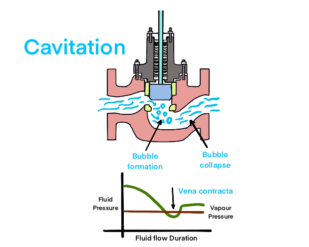

- Flashing: If the fluid pressure remains below the vapor pressure as it passes through the valve, the liquid turns into vapor. This two-phase flow (liquid and gas) can be highly erosive.
- Cavitation: If the pressure recovers to a point above the vapor pressure downstream of the valve, the vapor bubbles violently collapse (implode). This creates intense shockwaves that can cause severe damage to the valve trim and body.
Symptoms:
- Excessive noise: A sound often described as “gravel” or “marbles” flowing through the pipe is a classic sign of cavitation.
- Vibration: The implosion of vapor bubbles can cause significant vibration in the valve and surrounding piping.
- Rapid and severe trim erosion: The valve plug, seat, and even the valve body can be pitted and eroded in a very short time.
- Reduced flow capacity: The formation of vapor restricts the flow path, reducing the valve’s capacity.
- Pressure fluctuations: The process may become unstable due to the erratic nature of the cavitation.
Potential Causes:
- High pressure drop across the valve: The primary cause of both flashing and cavitation.
- Fluid temperature close to its boiling point: This reduces the pressure drop required to cause flashing.
- Improper valve selection or sizing: Using a valve not designed for high-pressure drop applications.
Troubleshooting Steps:
- Confirm the Phenomenon: Listen for the characteristic noise and feel for vibration. Analyze the process conditions (inlet pressure, outlet pressure, fluid temperature, and vapor pressure) to determine if cavitation or flashing is likely.
- Process Condition Adjustments (if possible):
- Increase downstream pressure: Raising the pressure downstream of the valve can prevent the pressure from recovering above the vapor pressure, thus preventing cavitation (though flashing may still occur).
- Decrease inlet pressure: Reducing the pressure drop across the valve is the most effective way to eliminate the problem.
- Lower fluid temperature: This increases the margin between the fluid pressure and its vapor pressure.
- Install a Downstream Orifice Plate: A fixed orifice plate downstream can share the total pressure drop, reducing the drop across the control valve itself.
- Use Anti-Cavitation Trim: This is the most robust solution. Anti-cavitation trims are specially designed to manage the pressure drop in multiple stages, preventing the local pressure from ever falling below the fluid’s vapor pressure.
- Select a Different Valve Type: For severe applications, consider using a valve specifically designed for high-pressure drop and cavitation resistance, such as a multi-stage or angle-seat control valve.
4. Actuator Failure:
The actuator is the “muscle” of the control valve, providing the force needed to move the valve’s obturator. Actuator failures can be pneumatic, electric, or hydraulic in nature.
Symptoms:
- Valve fails to open or close: The valve remains in its last position regardless of the control signal.
- Sluggish or slow response: The valve moves much slower than it should.
- Valve does not fully open or close: The actuator lacks the force to complete the full stroke.
- Air/hydraulic fluid leaks: Visible or audible leaks from the actuator.
- Actuator overheating (electric).
Potential Causes:
- Pneumatic Actuators:
- Loss of air supply: A common issue due to blocked lines, a failed compressor, or a closed isolation valve.
- Diaphragm or seal failure: A ruptured diaphragm or worn seals will cause a loss of actuating pressure.
- Sticking solenoid valve: The solenoid that directs air to the actuator may be stuck.
- Water or contaminants in the air supply: This can cause corrosion and sticking of internal components.
- Electric Actuators:
- Loss of power: A blown fuse, tripped breaker, or damaged wiring.
- Motor burnout: The electric motor has failed.
- Failed limit switches: The switches that signal the end of travel may be broken or misaligned.
- Damaged gearing: The internal gears that translate motor rotation into linear motion may be stripped or broken.
Troubleshooting Steps:
- Check the Power/Air Supply: This is the first and simplest check. For pneumatic actuators, verify the air pressure at the actuator. For electric actuators, confirm that power is being supplied.
- Inspect for Leaks: For pneumatic and hydraulic actuators, listen and feel for leaks. Use a soap solution to pinpoint air leaks.
- Check the Control Signal: Verify that the actuator is receiving the correct control signal from the positioner or control system.
- Test the Solenoid Valve (Pneumatic): Manually energize the solenoid to see if it clicks and directs air flow correctly.
- Isolate and Bench Test: If the issue is not obvious, remove the actuator from the valve. Attempt to operate the actuator without the load of the valve. This will determine if the problem lies with the actuator or the valve itself (e.g., severe stiction).
- Inspect Internal Components: If the actuator fails the bench test, disassemble it according to the manufacturer’s instructions. Inspect diaphragms, seals, O-rings, springs (pneumatic), or the motor, gears, and wiring (electric). Replace any worn or damaged components.
5. Positioner Problems: The Communication Breakdown
The valve positioner is the “brain” of the valve assembly, translating the electronic control signal into the precise amount of air pressure needed to move the actuator to the desired position. A faulty positioner can lead to a complete loss of control.
Symptoms:
- Valve does not respond to control signal changes.
- Incorrect valve position: The valve moves to a position that does not correspond to the control signal.
- Valve “hunts” or oscillates continuously.
- Non-linear response: The relationship between the control signal and the valve position is not linear.
Potential Causes:
- Loss of power or signal: The positioner may not be receiving power or the 4-20mA (or other) control signal.
- Clogged nozzles or restrictions: Debris in the air supply can block the small orifices within the positioner, affecting its output.
- Incorrect calibration: The positioner may have lost its calibration and no longer accurately relates the input signal to the valve’s position.
- Feedback linkage issues: The mechanical linkage that tells the positioner the valve’s actual position may be loose, bent, or broken.
- Electronic component failure: The internal electronics of the positioner can fail.
Troubleshooting Steps:
- Check Power and Input Signal: Verify that the positioner has the correct power supply and is receiving the control signal from the DCS or PLC.
- Inspect Air Supply and Gauges: Ensure the air supply is clean, dry, and at the correct pressure. Check the positioner’s supply and output gauges to see how it’s responding to signal changes.
- Inspect the Feedback Linkage: Ensure the feedback arm is securely connected to both the positioner and the valve stem and that it moves freely without excessive play.
- Check for Clogged Orifices: If the positioner is not outputting air, disconnect the air supply and carefully check for and clean any blockages in the nozzles and restrictions.
- Perform a Calibration: The most common solution for positioner issues is recalibration. Follow the manufacturer’s procedure to calibrate the zero, span, and linearity of the positioner. Modern smart positioners often have auto-calibration functions that simplify this process.
- Bypass the Positioner: As a temporary diagnostic step, you can bypass the positioner and apply air directly to the actuator to see if the valve moves. This helps confirm that the actuator and valve are mechanically sound.
- Replace the Positioner: If calibration fails and all other checks are clear, the positioner’s internal components may have failed, requiring a replacement.
6. Erosion and Corrosion: The Slow Degradation
Erosion is the physical wearing away of material due to the force of the process fluid (especially if it contains solid particles). Corrosion is the chemical degradation of material due to a reaction with the process fluid. Both lead to a gradual but certain failure of the valve.
Symptoms:
- External signs: Pitting, rust, or thinning of the valve body or bonnet.
- Internal leakage: The sealing surfaces of the trim are worn away.
- Loss of flow control: The valve’s characteristic is altered as the trim profile changes.
- Mechanical failure: In extreme cases, the valve body can be breached, or the stem can fail due to thinning.
Potential Causes:
- Erosion:
- Abrasive particles in the fluid: Sand, slurry, or catalyst fines.
- High fluid velocities: Especially in flashing or cavitating conditions.
- Corrosion:
- Incompatible materials: The valve’s materials of construction are not resistant to the chemical properties of the process fluid.
- High temperatures: Often accelerate corrosion rates.
- Galvanic corrosion: Occurs when dissimilar metals are in contact in the presence of an electrolyte.
Troubleshooting and Mitigation:
- Material Selection: This is a preventative measure but is the most critical factor. Ensure the valve materials (body, trim, and bolting) are appropriate for the process fluid, temperature, and pressure. Consult corrosion data tables and material specialists.
- Fluid Filtering: If the process fluid contains solid particles, install a strainer or filter upstream of the control valve.
- Control Fluid Velocity: If possible, use larger pipe sizes to reduce fluid velocity. For high-pressure drop applications where velocity will be high, use hardened trim materials.
- Hardened Trim and Coatings: For erosive services, specify valves with hardened trim materials like Stellite™, tungsten carbide, or ceramics. Special coatings can also be applied to the valve body to resist corrosion.
- Regular Inspection: Implement a regular inspection program, using techniques like ultrasonic thickness testing, to monitor the rate of material loss and predict when replacement will be necessary.
7. Incorrect Valve Sizing: The Misfit
A control valve that is improperly sized for the application will never perform well and will often lead to other failures.
- Oversized Valve: An oversized valve will operate very close to the closed position for most of the process. This leads to poor control, as a small change in valve position results in a large change in flow. It also causes “wire drawing” – high-velocity flow through the small opening, which rapidly erodes the seat and plug.
- Undersized Valve: An undersized valve will not be able to pass the required flow, even when fully open. It essentially acts as a restriction in the line, preventing the process from reaching its desired rate.
Symptoms:
- Oversized Valve:
- Process is difficult to control; constant oscillations.
- Valve operates at very low opening percentages (e.g., <10-15%).
- Rapid trim erosion.
- Undersized Valve:
- Inability to reach the process setpoint.
- Valve operates at or near 100% open.
- High pressure drop across the valve, potentially leading to cavitation.
Troubleshooting and Correction:
- Review Sizing Calculations: The only way to be sure about sizing is to perform a proper valve sizing calculation. This requires detailed process data, including flow rates (minimum, normal, and maximum), inlet and outlet pressures, fluid properties (density, viscosity), and temperature.
- Install a Position Transmitter: If not already installed, a position transmitter will show the actual operating position of the valve, which can help diagnose oversizing.
- Use Reduced-Capacity Trim: For an oversized valve, the most cost-effective solution is often to install reduced-capacity or restricted trim. This uses a smaller port size within the same valve body, effectively resizing the valve without needing to replace the entire unit.
- Replace the Valve: For an undersized valve, the only solution is to replace it with a correctly sized valve that can meet the process flow requirements.
By understanding these seven common control valve failures and arming yourself with a systematic troubleshooting approach, you can significantly reduce downtime, improve process efficiency, and ensure a safer operating environment. Regular preventative maintenance, coupled with a keen eye for the early symptoms of failure, is the key to keeping these critical assets in peak condition.