Ultrasonic Flowmeter Working Principle
Executive Summary
This report provides a comprehensive and in-depth analysis of ultrasonic flow meters, a class of non-invasive instruments that measure fluid velocity and, by extension, volumetric flow rate. The document dissects the two primary working principles—Transit-Time and Doppler Shift—and details their respective applications, advantages, and limitations. It explores critical operational factors that impact accuracy, such as flow profile, fluid properties, and installation conditions. A substantial portion of the report is dedicated to a comparative analysis, contrasting ultrasonic meters with other major flow metering technologies like magnetic, vortex, and Coriolis meters, to provide a strategic framework for selecting the optimal solution for specific industrial and commercial applications.
1. Introduction to Utrasonic Flowmeter Working Principle
1.1 Definition and Core Principle
An ultrasonic flow meter is an instrument that measures the velocity of a fluid by using sound waves at frequencies beyond the range of human hearing, typically in the megahertz range. This measurement is then used to calculate the volumetric flow rate of the fluid. The fundamental principle is rooted in the interaction of these high-frequency sound waves with a moving fluid medium, allowing for the determination of flow by either measuring the difference in transit time for pulses traveling with and against the flow, or by detecting the frequency shift of a signal reflected off moving particles within the fluid. This technology, which can be implemented with both intrusive and non-intrusive transducer arrangements, provides a highly adaptable solution for a variety of industrial and commercial applications.
1.2 Key Advantages of the Technology
The utility of ultrasonic flow meters is defined by several key advantages that differentiate them from many traditional measurement technologies. A primary benefit is their non-intrusive and non-contact nature, particularly in the case of clamp-on varieties. This configuration allows for the transducers to be mounted on the exterior of the pipe without any need to penetrate the pipe wall or interrupt the process. This eliminates common drawbacks associated with in-line meters, such as pressure loss, fluid leaks, and the potential for sensor corrosion or deterioration from contact with the measured fluid.
Furthermore, ultrasonic flow meters are recognized for their minimal maintenance requirements. The absence of any moving parts, such as those found in turbine meters, means there are no components subject to mechanical wear or bearings that need to be replaced over time. This design choice contributes to a high degree of reliability and significantly reduces long-term operational costs. The technology is also highly versatile, capable of measuring a wide array of fluids, including liquids, gases, and steam, and is available in various configurations to suit different needs, from clamp-on to inline and even open-channel models. If you are preparing for interview refer to https://www.youtube.com/watch?v=WidyT99gG5M for top 20 question and answers for ultrasonic flowmeter.
The foundational value proposition of ultrasonic flow meters is rooted in a strategic trade-off. By foregoing moving parts and direct fluid contact, the technology minimizes mechanical wear and maintenance requirements. This is a direct causal relationship: a meter without moving parts cannot be subject to mechanical failure from those parts. However, this non-contact approach places an increased reliance on precise physical and acoustic measurements, which are highly sensitive to installation and environmental factors. This introduces a critical nuance: while the meter itself may be “maintenance-free,” the system’s accuracy is critically dependent on a meticulous initial setup and calibration. The overall benefit of low maintenance is thus contingent on a high-quality installation, where any errors in pipe parameters, transducer alignment, or environmental noise can render the meter inaccurate or inoperable. Consequently, the initial investment is less about the hardware and more about the correct implementation and engineering of the system.
2. The Physics of Ultrasonic Flow Measurement
The operational principles of ultrasonic flow meters are categorized into two primary technologies: the Transit-Time principle and the Doppler Shift principle. Each is a distinct application of physics tailored for specific fluid characteristics.
2.1 The Transit-Time (Time-of-Flight) Principle
2.1.1 Core Mechanism
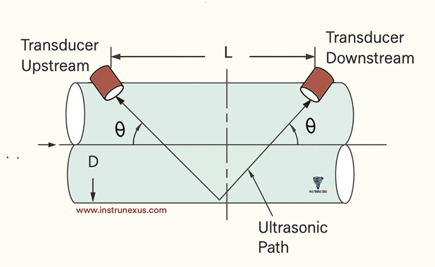
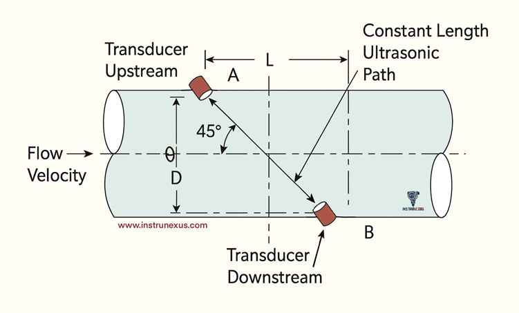
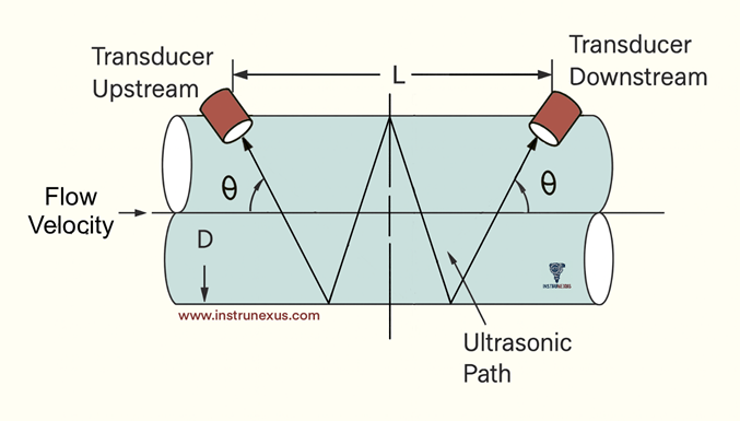
The Transit-Time, or Time-of-Flight, principle is based on measuring the difference in the time it takes for an ultrasonic pulse to travel with and against the direction of fluid flow. A typical setup employs two transducers that function as both transmitters and receivers, alternately sending and receiving a burst of ultrasound energy. The pulse traveling downstream, with the fluid flow, arrives at its destination sooner than the pulse traveling upstream, against the flow. This measured time difference () is directly proportional to the average velocity of the fluid along the path of the ultrasonic beam. This method is sometimes referred to ascontrapropagating transit-time.
2.1.2 Mathematical Derivations
The relationship between the measured transit times and the fluid’s velocity is described by a set of governing equations. If is the time for the pulse to travel downstream and is the time for the pulse to travel upstream, the two can be expressed as:
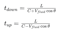
where is the distance between the transducers, is the speed of sound in the fluid, and is the inclination angle of the transducers relative to the pipe.
By adding and subtracting these equations, the average fluid velocity () and the speed of sound () can be calculated. A key aspect of this technology is that by measuring both transit times, the meter can compute the fluid’s velocity without requiring prior knowledge of the speed of sound in the fluid. This is significant because the speed of sound can be influenced by factors such as temperature, density, and viscosity. The equations can also be manipulated to calculate the speed of sound as a byproduct of the measurement.
2.1.3 Transducer Configurations
For clamp-on transit-time meters, transducers can be mounted in three common single-path configurations, known as Z, V, and W methods.
V-method: This is the most prevalent configuration. The ultrasound signal is transmitted from the first transducer, travels through the pipe wall and the fluid, and then reflects off the back wall of the pipe to be received by the second transducer. This is a 2-pass configuration.
Z-method: In this single-pass configuration, the transducers are mounted directly opposite each other on the pipe. This method is often preferred for large pipe diameters, as it reduces the required path length.
W-method: This is a multi-pass configuration that increases the path length of the ultrasonic signal. It is particularly useful for very small pipe diameters where the path length is otherwise too short to generate a measurable time difference.
The choice of configuration depends on several factors, including the pipe size, the available space for mounting, the condition of the pipe’s internal walls, and the specific characteristics of the fluid.
2.1.4 Fluid Compatibility
The Transit-Time principle is critically dependent on a “clear path” for the ultrasonic signal to travel from the transmitter to the receiver. This makes the technology ideal for homogeneous, acoustically conductive fluids that are free from a high concentration of air bubbles or suspended solids, as these can interfere with or block the signal. Applications for this technology are typically with clean liquids, such as water, chemicals, and oils, as well as gases.
2.2 The Doppler Shift Principle
2.2.1 Core Mechanism
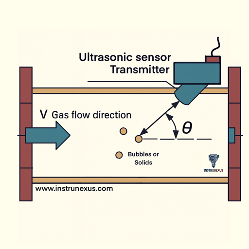
In contrast to the Transit-Time method, the Doppler Shift principle operates by transmitting an ultrasonic signal into the fluid and measuring the change in frequency (the Doppler Effect) of the signal that is reflected back. The frequency shift is directly proportional to the velocity of the reflecting objects within the fluid. These “sonically reflective materials” can be solid particles, entrained air bubbles, or even turbulent eddies in the fluid itself.
2.2.2 Fluid Compatibility
The Doppler principle is fundamentally dependent on the presence of these reflective objects to function accurately. This makes Doppler meters the ideal choice for applications involving “dirty fluids” such as slurries, liquids with a high concentration of bubbles, or gases with sound-reflecting particles. The technology is particularly useful in environments where a Transit-Time meter would fail due to signal disruption.
The relationship between Transit-Time and Doppler technologies is not one of competition but of complementarity. They serve distinct fluid-based applications, with a clear dividing line based on the presence of entrained particles or bubbles. The “clear path” requirement for Transit-Time meters is a direct limitation, forcing engineers to select Doppler meters for “dirty” fluids. This highlights a fundamental design choice where the physical principle of measurement directly dictates the application’s suitability. The engineer’s first step in selecting a meter is to analyze the fluid’s acoustic properties and presence of entrained particles. This single fluid characteristic is the primary determinant for the choice between these two ultrasonic technologies. Click here to see the difference between Transit time and Doppler Effect flowmeters
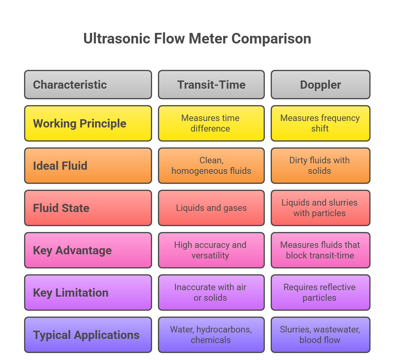
Table 1: Ultrasonic Flow Meter Technologies: A Comparative Overview
3. Practical and Operational Considerations
The reliability and accuracy of an ultrasonic flow meter extend beyond its core physical principles and are critically dependent on practical and operational factors. The theme of meticulous installation and calibration underpins the technology’s performance.
3.1 Factors Influencing Measurement Accuracy
3.1.1 Flow Profile and Installation
As velocity-based instruments, ultrasonic flow meters are highly dependent on a stable, fully developed flow profile within the pipe. For this reason, manufacturers specify a minimum length of straight pipe both upstream and downstream of the meter. If the installation site does not meet these requirements, the flow profile may become unstable, leading to significant measurement errors.
Flow disturbances are a common cause of accuracy and repeatability issues. Obstructions such as elbows, tees, reducers, and partially closed valves can create irregular flow patterns, including asymmetric velocity profiles and swirl. Swirl, an asymmetric profile with a single vortex, can persist for numerous pipe lengths and create significant measurement errors. A properly executed installation is essential to mitigate these effects.
3.1.2 Fluid and Pipe Parameters
The accuracy of the volumetric flow calculation is heavily reliant on the correct input of key pipeline parameters. This includes the pipe’s inner diameter, which is a particularly sensitive parameter since the flow rate is proportional to the square of the diameter. Even small errors in the diameter input can have a magnified effect on the flow rate reading, especially in smaller pipes. The accuracy of the measurement is also affected by the acoustic properties of the fluid, such as temperature, density, and viscosity.
Additionally, the presence of a pipe lining, such as cement mortar or other coatings, must be accounted for. Linings may have irregular thickness or surface roughness, which can distort the ultrasonic signal and introduce substantial errors if not factored into the calibration and measurement process.
3.1.3 Environmental and Acoustic Interference
The performance of ultrasonic meters can be degraded by external environmental and acoustic interference. Sources of electromagnetic interference, such as high-voltage power lines, heavy traffic, or even mobile phones, can cause inaccuracies. The design of a transducer must also incorporate acoustic isolation to ensure the ultrasonic energy is effectively directed into the fluid stream rather than being lost to the surrounding metallic pipe. This is typically accomplished through the use of intermediate materials referred to as a “matching layer”.
3.2 Calibration and Maintenance
The principle of “no moving parts” leading to “low maintenance” is a powerful but potentially misleading simplification. The true understanding recognizes that the maintenance burden has shifted from mechanical to metrological. While a meter may be “virtually maintenance-free” in the sense that no parts need replacement , its performance is critically dependent on proper calibration. Each meter and transducer set has a specific correction factor determined during its calibration, and it is essential to ensure that the correct factor is applied during operation to avoid inaccurate results.
The initial installation, with its strict requirements for straight pipe runs, accurate pipe parameter input, and a noise-free environment, is the most critical and potentially demanding phase of the meter’s life cycle. This initial “cost” is a factor in the total cost of ownership (TCO) that extends beyond the hardware’s purchase price. The benefit of a clamp-on meter to avoid process shutdown is a clear TCO calculation, but it is contingent on a flawlessly executed installation that adheres to the metrological demands of the technology.
4. Applications Across Industrial Sectors
The versatility of ultrasonic technology—from clean water to dirty slurries, from high-pressure gases to open channels—is not a single capability but a portfolio of specialized solutions. An expert understands that the term “ultrasonic” encompasses a family of meters, each optimized for specific challenges.
4.1 General and Industrial Applications
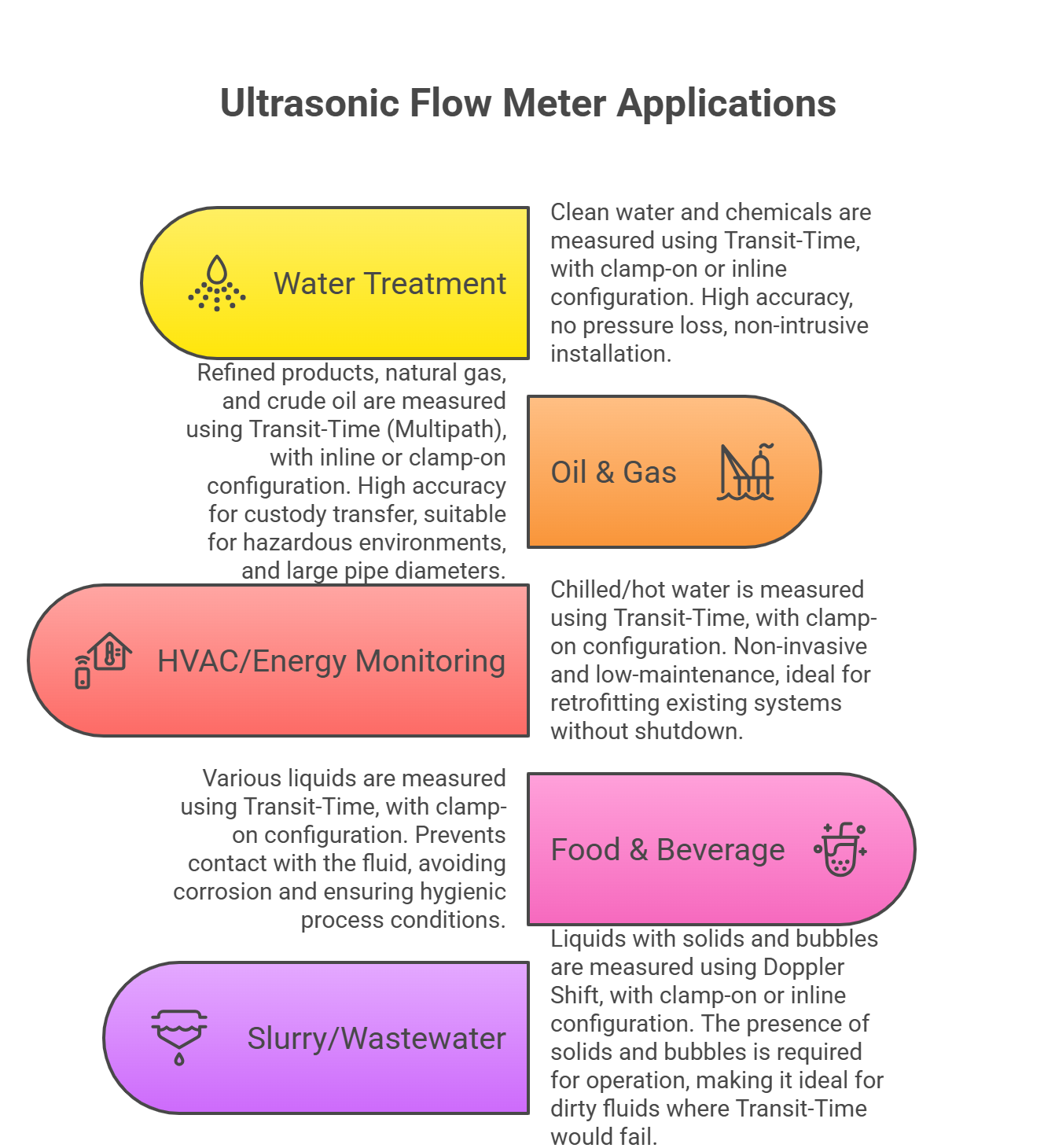
Water and Wastewater: Ultrasonic meters are widely used in municipal water and wastewater systems. Their non-intrusive nature allows for easy installation without process shutdown, making them an ideal choice for metering water and other fluids. They can also be adapted to handle the dirtier fluids found in wastewater applications.
Oil and Gas: The technology is critical in the oil and gas, hydrocarbon, and chemical processing industries. Ultrasonic meters are used for general process measurement and are even approved for custody transfer of natural gas and hydrocarbon liquids in large pipelines.
HVAC and Energy Monitoring: In commercial and residential settings, ultrasonic meters are used for HVAC and energy monitoring, where they measure the flow of chilled water, hot water, or other fluids. The non-invasive nature of clamp-on meters makes them particularly suitable for these applications.
Food and Beverage: The non-invasive nature of clamp-on meters is ideal for food and beverage processing, where contact with the product and the risk of contamination must be avoided.
4.2 Specialized Applications
Gases and Steam: Ultrasonic meters are specifically designed for measuring gas flow, including natural gas, compressed air, and biogas. They can also measure the mass flow rate of saturated or superheated steam, which is a key advantage as they avoid the pressure drop associated with intrusive meters.
Open Channels: For flow measurement in partially filled pipes or canals, ultrasonic sensors are used to measure the height of the fluid. The flow rate is then determined based on the known geometry of the channel.
Custody Transfer: For high-value, high-volume applications like the custody transfer of natural gas and hydrocarbon liquids, multipath ultrasonic meters are approved and widely used for their high accuracy.
The broad applicability of the technology is a second-order phenomenon that arises from the existence of the two complementary principles. A single ultrasonic meter cannot address all applications; rather, the term “ultrasonic” describes a family of solutions, each optimized for specific challenges. The correct selection for an application requires a detailed understanding of the fluid characteristics, which will then guide the choice of the appropriate technology sub-type (e.g., a clamp-on Transit-Time meter for HVAC vs. a Doppler meter for a mining slurry).
Table 2: Applications of Ultrasonic Flow Meters by Industry and Fluid Type
5. Comparative Analysis: Ultrasonic vs. Alternative Flow Meters
The choice of a flow meter is a classic engineering optimization problem, balancing performance, cost, and reliability. There is no single “best” technology, but rather a “best fit” for a given application. This section reveals the key trade-offs in selecting an ultrasonic meter over other major flow metering technologies.
5.1 Ultrasonic vs. Magnetic (Magmeters)
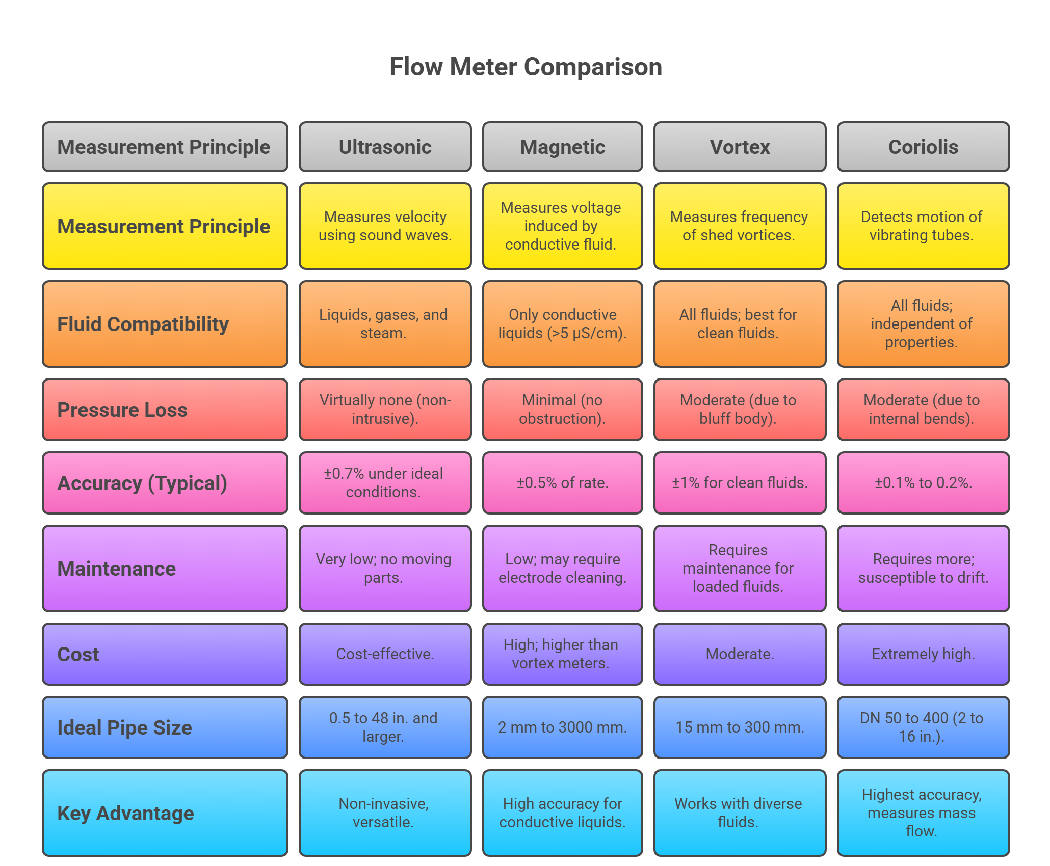
Magnetic flow meters measure flow by inducing a magnetic field and measuring the voltage produced by a conductive fluid moving through it. A key limitation is that they require an electrically conductive fluid to operate, making them unsuitable for hydrocarbons or pure water. While ultrasonic meters can measure these non-conductive fluids, magmeters are often a preferred choice for conductive liquids, such as water and acids, where they can offer slightly higher accuracy (typically 0.5% compared to 0.7% for ultrasonic meters under ideal conditions). Both technologies are velocity-based and require a full pipe for accurate measurement.
5.2 Ultrasonic vs. Vortex Flow Meters
Vortex flow meters measure fluid velocity by detecting the frequency of vortices shed by a bluff body obstruction placed in the flow path. This obstruction creates a moderate pressure drop across the meter. By contrast, ultrasonic meters exhibit virtually no pressure loss, as they do not obstruct the flow. While vortex meters are versatile and can measure liquids, gases, and steam, they are not effective at low flow rates, where the formation of vortices is insufficient for an accurate reading. Ultrasonic meters, on the other hand, can measure very low flow rates, as low as 0.5 ft/s. Vortex meters are often the preferred choice for steam systems and compressed air applications.
5.3 Ultrasonic vs. Coriolis Flow Meters
Coriolis meters represent a fundamentally different measurement principle, as they measure mass flow rather than volumetric flow. They operate by detecting the twisting motion of one or more vibrating tubes as fluid passes through them. Coriolis meters are known for their extreme accuracy (often 0.1% to 0.2%) and are not impacted by changes in fluid properties like temperature, density, or viscosity. This makes them the standard for high-value applications, such as custody transfer.
However, this extreme accuracy comes at a significant cost. Coriolis meters are notably more expensive and require more maintenance due to the vibrating tubes, which are susceptible to wear and pressure fluctuations. Ultrasonic meters are a more cost-effective and low-maintenance alternative, especially for applications where the extreme accuracy of a Coriolis meter is not required.
The expert decision-making process is not about a single metric but a holistic assessment of the entire application. The underlying physical principle of each meter directly dictates its limitations and advantages. For instance, the electromagnetic principle of a magmeter necessitates a conductive fluid, while the sound wave principle of an ultrasonic meter does not. The choice is a strategic one: is a marginal gain in accuracy worth a higher price and increased maintenance? Does the application require mass flow or volumetric flow? This analysis transforms the selection process from a simple comparison into a strategic decision guide.
Table 3: Comparative Analysis of Major Flow Meter Technologies
6. Conclusion and Strategic Recommendations
6.1 A Decision Matrix for Flow Meter Selection
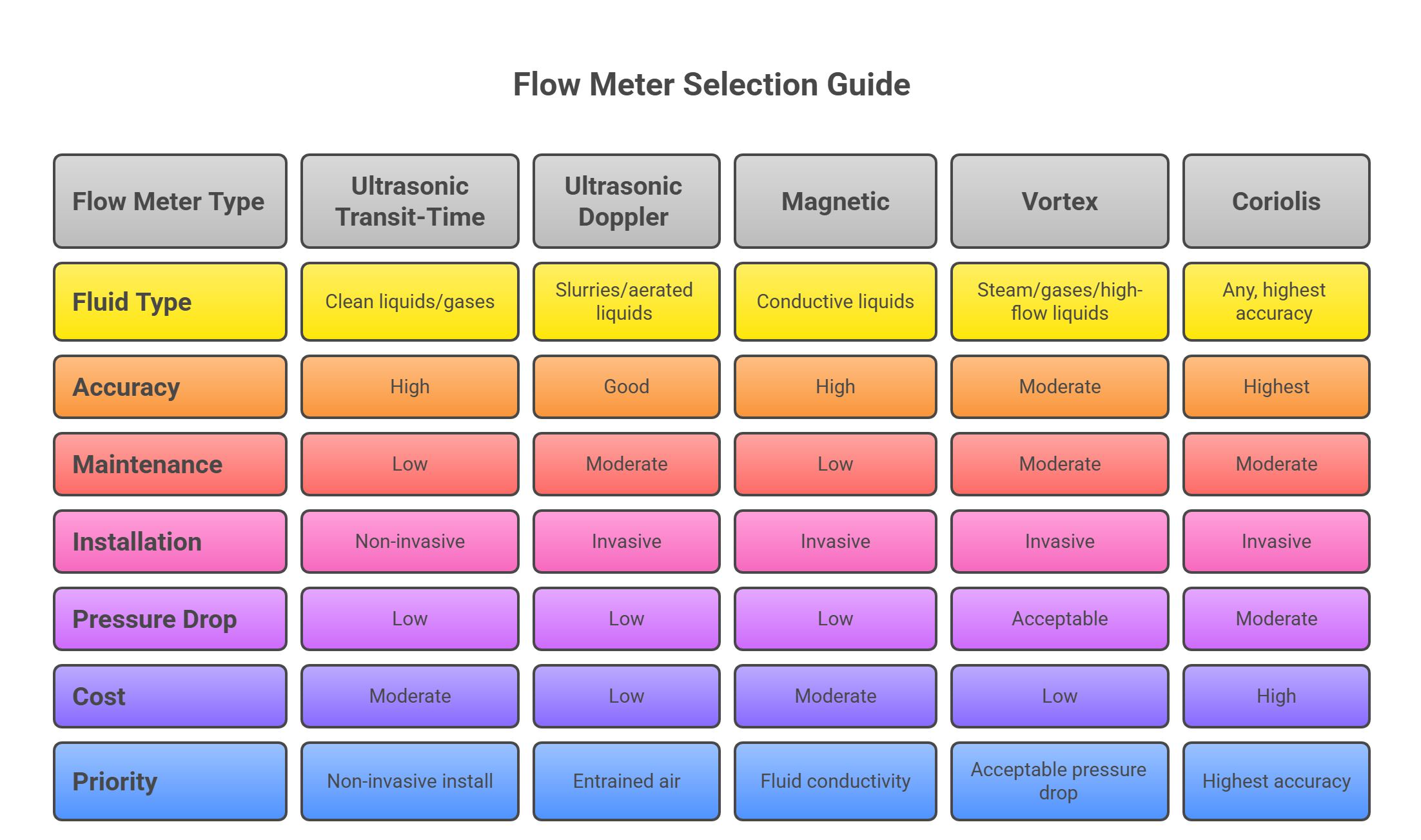
The selection of a flow meter should begin with a thorough analysis of the application’s requirements. The following decision matrix provides a clear guide for choosing the most appropriate technology:
For clean, homogeneous liquids and gases: An ultrasonic Transit-Time meter is a primary consideration, especially where a non-invasive installation is a priority, such as with large pipelines or hazardous fluids. This meter provides an excellent balance of high accuracy and low maintenance.
For slurries and liquids with high concentrations of entrained air: An ultrasonic Doppler meter is the most suitable choice, as its working principle is designed to function with, and in fact requires, these fluid properties.
For highly accurate measurement of conductive liquids: A magnetic flow meter may be a superior choice, provided the fluid’s conductivity and the installation conditions are suitable.
For steam, gases, and high-flow liquids where a pressure drop is acceptable: A vortex flow meter is often the most practical and reliable solution.
For applications requiring the highest possible accuracy, regardless of cost: A Coriolis meter is the standard, particularly for custody transfer or other high-value measurement points where a direct mass flow reading is required.
6.2 Strategic Recommendations
Based on the comprehensive analysis, ultrasonic flow meters represent a go-to solution for a wide range of modern industrial applications. Their non-intrusive nature, low maintenance burden, and broad fluid compatibility portfolio offer a compelling value proposition. However, this is contingent on recognizing that the reliability of the measurement has shifted from the mechanical integrity of the device to the metrological quality of its installation. The initial investment in ensuring a proper, compliant installation—including sufficient straight pipe runs, accurate pipe parameter input, and a noise-free environment—is crucial to realizing the full, long-term benefits of the technology.
6.3 Outlook
The future of ultrasonic flow metering is bright, with ongoing developments focused on enhancing accuracy and expanding its application envelope. Trends indicate continued advancements in transducer technology to improve signal-to-noise ratios, allowing for even greater accuracy and reliability in challenging environments. The integration of enhanced electronics and software is also paving the way for more sophisticated diagnostics and integration with smart industrial systems, further cementing the ultrasonic flow meter’s role as a cornerstone of modern fluid measurement. Ultrasonic Flowmeter Working Principle