Control valves are essential components in the regulation of fluid flows in the oil, gas, and process industries. They help in adjusting the flow rate of fluids within a system, which is critical for optimizing performance and ensuring safety. However, when flow conditions reach certain critical levels, problems like cavitation, flashing, and choked flow can occur, potentially leading to serious damage to the system, reduced performance, and safety hazards.
In this blog, we will delve deep into cavitation, flashing, and choked flow in control valves, explaining their causes, effects, and solutions for the oil & gas and process industries.
1. Introduction to Control Valves and Flow Control
Control valves are designed to regulate the flow of liquids, gases, and steam through pipelines and systems. They are typically located in systems where precise flow control is required, such as chemical plants, power plants, oil & gas facilities, and water treatment plants. These valves operate by adjusting the valve opening based on signals received from the process control system, typically a Distributed Control System (DCS) or a Supervisory Control and Data Acquisition (SCADA) system.
However, the valve’s ability to perform its job can be compromised if the operating conditions result in high velocity or pressure drop across the valve. This can lead to undesirable phenomena such as cavitation, flashing, and choked flow, which need to be understood and managed properly.
2. Cavitation in Control Valves
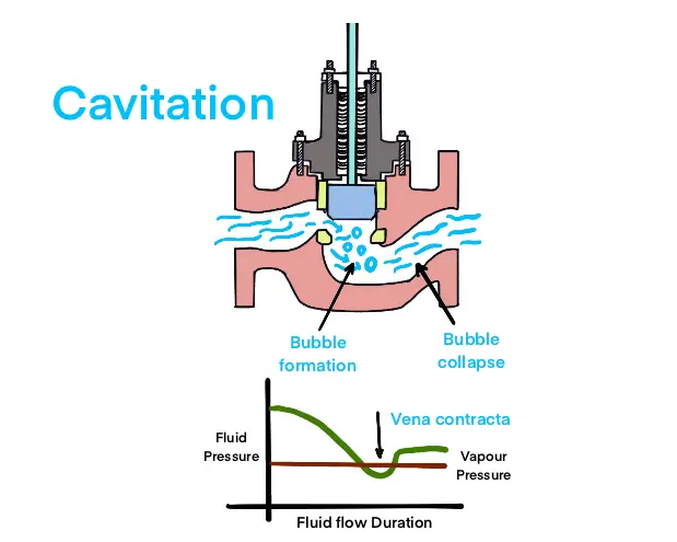
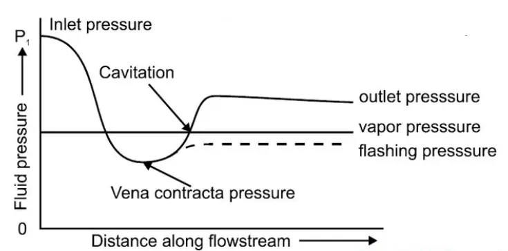
2.1 What is Cavitation?
Cavitation occurs when the pressure of a fluid drops below its vapor pressure, causing the formation of vapor bubbles inside the fluid stream. When these vapor bubbles are carried downstream into areas of higher pressure, they collapse violently, leading to localized shockwaves and intense energy release. This sudden collapse can cause damage to the valve components, such as the valve trim, body, and seat.
2.2 Causes of Cavitation
The primary cause of cavitation in control valves is a significant pressure drop across the valve, where the pressure in the flow stream falls below the vapor pressure of the fluid. This condition is most commonly found in systems where:
-
The pressure at the valve inlet is high, and the outlet pressure is low.
-
The flow rate is reduced, increasing the velocity of the fluid through the valve.
-
Fluids with low vapor pressures, such as water or hydrocarbons, are involved.
2.3 Effects of Cavitation
Cavitation can have several negative effects on both the control valve and the entire system:
-
Valve Damage: The implosion of vapor bubbles causes erosion, pitting, and fatigue of the valve trim, leading to premature wear and failure.
-
Flow Instability: Cavitation can cause unstable flow and fluctuations in pressure, negatively affecting the process control.
-
Noise and Vibration: Cavitation can generate high-frequency noise and vibrations, which can cause additional mechanical stresses on the valve and other system components.
2.4 Preventing Cavitation
To avoid cavitation, operators can implement several strategies:
-
Reduce Pressure Drop: Ensure that the pressure drop across the valve does not exceed the vapor pressure of the fluid. This can be achieved by selecting the correct valve size or using pressure-reducing devices.
-
Use Anti-Cavitation Valves: These valves are designed with features such as multi-stage trims or cages that reduce the pressure drop gradually, preventing the conditions that lead to cavitation.
-
Incorporate Back-Pressure Regulators: These devices can maintain a minimum pressure at the valve outlet, ensuring that the fluid pressure does not fall below the vapor pressure.
-
Select Proper Valve Size: Oversized valves may cause excessive pressure drops, leading to cavitation. Proper sizing helps in minimizing cavitation risks.
3. Flashing in Control Valves
3.1 What is Flashing?
Flashing is similar to cavitation, but the difference lies in the nature of the phase change of the fluid. While cavitation involves the formation of vapor bubbles that collapse, flashing occurs when the pressure at the valve outlet is reduced so significantly that the liquid instantly vaporizes, turning into gas or vapor as it passes through the valve. The presence of vapor bubbles can lead to rapid changes in the flow characteristics and can result in significant energy loss.

3.2 Causes of Flashing
Flashing is typically caused by:
-
Excessive Pressure Drop: A large pressure drop from a high-pressure liquid to a low-pressure vapor can induce flashing. This occurs when the outlet pressure is significantly lower than the fluid’s vapor pressure.
-
Temperature Effects: Increased temperature of the fluid can lower its vapor pressure, increasing the likelihood of flashing.
-
High Flow Rates: Fast-moving fluids through a control valve may lead to sudden reductions in pressure, facilitating flashing.
3.3 Effects of Flashing
The effects of flashing on control valves and processes are similar to cavitation but can be more severe:
-
Erosion: The rapid phase change and the resulting formation of vapor bubbles can lead to erosion and pitting on the valve surfaces, particularly on trim components.
-
Noise: Flashing causes loud, distinct noises due to the rapid formation of vapor bubbles and their collapse, similar to cavitation.
-
Pressure Fluctuations: Flashing can result in unstable flow conditions, leading to fluctuations in pressure and flow rate.
-
Reduced Flow Control: The presence of vapor reduces the effective area for fluid flow, which can result in less predictable control and poor performance in the process.
3.4 Preventing Flashing
To mitigate flashing, the following methods can be used:
-
Increasing Outlet Pressure: By increasing the pressure downstream of the valve, the likelihood of flashing can be reduced.
-
Using Flashing-Resistant Valves: Some valves are designed with features that minimize the chances of flashing by allowing the vapor to exit in a controlled manner.
-
Install Pressure-Reducing Valves: These can help maintain the required pressure in the system and prevent flashing conditions.
-
Correct Valve Sizing: As with cavitation, proper valve sizing ensures that the pressure drop is within acceptable limits to prevent flashing.
4. Choked Flow in Control Valves
4.1 What is Choked Flow?
Choked flow occurs when the velocity of the fluid at the valve reaches the speed of sound (sonic velocity). When this happens, any further increase in the flow rate is no longer possible, as the flow becomes constrained by the conditions at the valve. The flow rate becomes limited by the valve’s capacity to pass the fluid, and any increase in pressure drop upstream of the valve does not result in a proportional increase in flow.
4.2 Causes of Choked Flow
Choked flow typically occurs in gas systems, particularly in applications involving natural gas, compressed air, or other gases. The primary causes of choked flow are:
-
High Flow Rates: When the gas is flowing at very high velocities, it may approach the speed of sound, which results in choked flow.
-
Reduced Pressure Downstream: Choked flow occurs when the downstream pressure is low enough to allow the fluid velocity to reach sonic conditions.
-
Valve or Piping Restrictions: Inadequate valve size or narrow pipe diameters may restrict the flow of gas, creating conditions conducive to choked flow.

4.3 Effects of Choked Flow
The effects of choked flow are critical in many gas handling systems:
-
Flow Limitation: Once choked flow is reached, further increases in upstream pressure cannot increase flow, which limits the control over the system.
-
Energy Loss: Choked flow represents a loss of potential energy because the system cannot utilize additional pressure to increase flow.
-
System Instability: Choked flow can cause operational instability, especially in processes requiring precise flow regulation and control.
4.4 Preventing Choked Flow
To avoid choked flow:
-
Proper Valve Sizing: Ensure the valve is sized appropriately for the expected flow conditions. Oversized or undersized valves may lead to choked flow.
-
Use of Pressure Regulators: Installing a downstream pressure regulator can help prevent the system from reaching conditions conducive to choked flow.
-
High-Flow Valves: Some valves are designed specifically to handle high-flow rates without causing choking, thus preventing sonic velocities from being reached.
5. Conclusion
In the oil, gas, and process industries, understanding the causes, effects, and solutions for control valve cavitation, flashing, and choked flow is crucial for maintaining system reliability and performance. These phenomena not only impact valve performance but can also lead to significant damage, energy losses, and operational instability. By implementing proper valve sizing, utilizing anti-cavitation technologies, ensuring stable downstream pressures, and monitoring system conditions, these issues can be mitigated, leading to more efficient and reliable process operations.
Proper training, regular maintenance, and detailed system design are essential in preventing cavitation, flashing, and choked flow, ensuring the long-term health and performance of control valve systems in critical process environments.