Introduction
The Displacer Type Level Transmitter is a widely used level measurement device in the oil & gas, chemical, and power generation industries. It operates based on the principle of Archimedes’ Law, which states that a body submerged in a fluid experiences a buoyant force equal to the weight of the fluid it displaces. The transmitter senses this force change through a mechanical or electronic system and converts it into a level signal.
This type of level transmitter is especially suitable for applications involving high temperatures, high pressures, or corrosive fluids and is used to measure the level of liquids in tanks, vessels, or columns.
Basic Construction
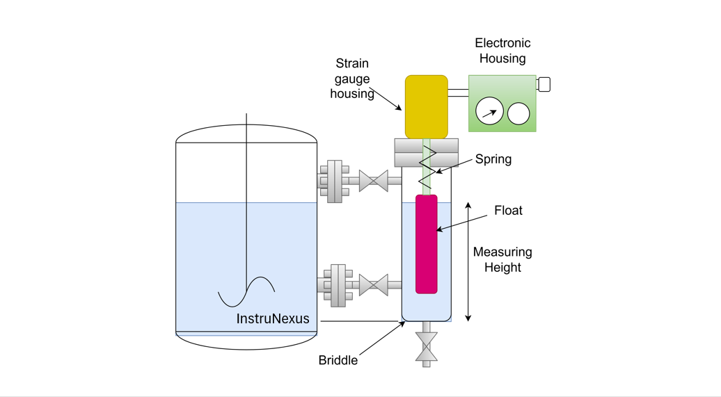
A typical Displacer Type Level Transmitter consists of the following main components:
-
Displacer Element: A cylindrical or rod-shaped solid body made of stainless steel or other suitable material, suspended in the tank where level measurement is required.
-
Torque Tube Assembly: Connects the displacer to a pivot arm and allows rotational movement in response to buoyant forces.
-
Range Spring and Magnetic Coupling: Balances the force and transmits the motion to the sensing element.
-
Transmitter Housing: Contains the sensor mechanism and electronics that convert mechanical motion into an electrical output (e.g., 4–20 mA).
-
Flange or Cage Mounting: The transmitter may be mounted directly into the vessel or externally through a side-mounted cage.
Working Principle
1. Buoyant Force and Archimedes’ Principle
When the displacer is suspended in the process fluid, it displaces a volume of liquid. According to Archimedes’ Principle:
Buoyant Force (Fb) = Weight of Displaced Liquid
As the liquid level in the tank rises or falls, the volume of liquid displaced by the displacer changes. This changes the net force acting on the displacer, which leads to a mechanical movement.
2. Force Balance and Torque Tube Movement
-
At lower liquid levels, only a small portion of the displacer is submerged, and the buoyant force is less.
-
As the level rises, more of the displacer gets submerged, increasing the buoyant force acting upward.
-
This causes a torque in the torque tube assembly, which is proportional to the change in buoyant force.
The torque tube twists accordingly, and this rotation is directly proportional to the liquid level in the vessel.
3. Signal Transmission
-
The mechanical displacement is either directly transmitted to a pointer (in local indicators) or converted into an electrical signal using electronic sensors and transmitters.
-
Modern displacer level transmitters use Hall-effect sensors or LVDTs (Linear Variable Differential Transformers) to convert the mechanical motion into a 4–20 mA output.
-
The transmitter can also be connected to a DCS or PLC for continuous monitoring and control.
Mathematical Representation
Let:
-
Vd = Volume of displacer submerged
-
ρ = Density of liquid
-
g = Gravitational acceleration
Then,
Buoyant Force:
Fb=ρ⋅g⋅Vd
As the fluid level increases, Vd increases, and so does Fb. This change is what the transmitter senses and translates into a proportional signal.
Application Considerations
Advantages:
-
Suitable for high pressure and high temperature.
-
Can be used in dirty or viscous liquids.
-
Immune to foam and vapor layers.
Limitations:
-
Mechanical parts are prone to wear over time.
-
Calibration required when fluid density changes.
-
Not ideal for rapid level changes or slurry applications.
Installation Types
-
Cage Mounted: For external measurement with isolation valves—ideal for maintenance and safety.
-
In-Tank Mounted: Displacer suspended directly inside the tank—used where cage mounting is not feasible.
Use Cases in Industry
-
Oil & Gas: Level measurement in separators, knock-out drums, or reflux drums.
-
Petrochemical: Interface level detection in multi-phase separators.
-
Power Plants: Condensate and feedwater tank level control.
-
Chemical Plants: Measurement in reactors or solvent tanks.
Displacer vs Other Level Technologies
| Feature | Displacer Type | Radar/Ultrasonic | DP Transmitter |
|---|---|---|---|
| Principle | Buoyancy (Archimedes’) | Time-of-flight/Reflection | Pressure differential |
| Contact/Non-contact | Contact | Non-contact | Contact (via impulse lines) |
| Temperature/Pressure Suitability | High | Moderate to High | High |
| Maintenance | Mechanical parts wear | Low | Impulse line clogging |
| Cost | Medium | High | Low to Medium |
Conclusion
Displacer Type Level Transmitters are reliable and time-tested instruments that provide accurate level measurements, especially under challenging process conditions. While newer technologies like radar and ultrasonic are gaining popularity, displacer transmitters still hold a vital place in process industries due to their ruggedness and versatility. Proper installation and calibration ensure accurate, repeatable performance in a wide range of applications.