1oo2 Safety Architecture under IEC 61511
In the world of the process industry—be it oil and gas, chemical manufacturing, or power generation—safety isn’t just a priority; it’s the foundation upon which operational integrity is built. A catastrophic failure can have devastating consequences for human life, the environment, and business continuity. This is where Functional Safety standards like IEC 61511 come into play, providing a systematic framework to manage risks. A cornerstone of this framework is the Safety Instrumented System (SIS), and at the heart of the SIS lies its architecture.
One of the most widely discussed and implemented configurations is the 1oo2 (One-out-of-Two) safety architecture. It represents a critical balance between safety and operational availability. But what exactly is it? How does it work, how is its performance calculated, and when is it the right choice for your application?
This comprehensive guide will delve into the intricacies of the 1oo2 architecture as defined by IEC 61511. We’ll explore its design, voting logic, benefits, drawbacks, and the crucial calculations that underpin its reliability. Whether you’re a process safety engineer, an instrumentation technician, or a plant manager, understanding the 1oo2 architecture is fundamental to achieving robust and compliant safety solutions.
What is a Safety Instrumented System (SIS)?
Before we dissect the 1oo2 architecture, let’s establish the context. A Safety Instrumented System (SIS) is an independently automated system designed to bring a process to a safe state when predetermined conditions are violated. It acts as a critical layer of protection, separate from the basic process control system (BPCS), which manages the day-to-day operations of the plant.
An SIS is composed of one or more Safety Instrumented Functions (SIF). Each SIF has three core components:
-
Sensors: These devices (e.g., pressure transmitters, temperature sensors, level switches) monitor the process variables.
-
-
Logic Solver: This is the “brain” of the SIF (often a safety PLC) that processes the input from the sensors and decides whether to act.
-
Final Elements: These devices (e.g., emergency shutdown valves, relief valves, pumps) execute the action determined by the logic solver to bring the process to a safe state.
The reliability of an SIS is quantified by its Safety Integrity Level (SIL), which ranges from SIL 1 (lowest integrity) to SIL 4 (highest). The required SIL for a given SIF is determined through risk assessment methodologies like a Layer of Protection Analysis (LOPA). The chosen architecture is a primary factor in achieving the target SIL.
Understanding IEC 61511: The Global Standard
IEC 61511, “Functional Safety – Safety Instrumented Systems for the process industry sector,” is the definitive international standard for managing the entire lifecycle of an SIS. It covers everything from initial hazard and risk assessment to the design, implementation, operation, maintenance, and eventual decommissioning of safety systems.
A key concept within IEC 61511 is Hardware Fault Tolerance (HFT). HFT is the ability of a system to continue performing its required function in the presence of one or more hardware faults. An HFT of ‘N’ means the system can tolerate ‘N’ faults and still function safely. The required HFT is directly linked to the target SIL of the function. This is where different architectural configurations come into play.
-
1oo1 (One-out-of-One): HFT of 0. A single channel system. If the one component fails, the SIF fails.
-
1oo2 (One-out-of-Two): HFT of 1. A two-channel system where either channel can trip the process.
-
2oo2 (Two-out-of-Two): HFT of 0. A two-channel system where both channels must agree to trip.
-
2oo3 (Two-out-of-Three): HFT of 1. A three-channel system where two out of the three channels must agree to trip.
The choice of architecture is a trade-off between safety, availability, and cost. The 1oo2 architecture is a popular choice because it significantly improves safety over a simple 1oo1 system.
Deep Dive into the 1oo2 Architecture 
The 1oo2 architecture consists of two independent channels, each capable of detecting a hazard and initiating a trip. The “1-out-of-2” voting logic means that if either Channel A OR Channel B detects a hazardous condition, the logic solver will command the final element to move the process to a safe state.
How it Works: The Voting Logic
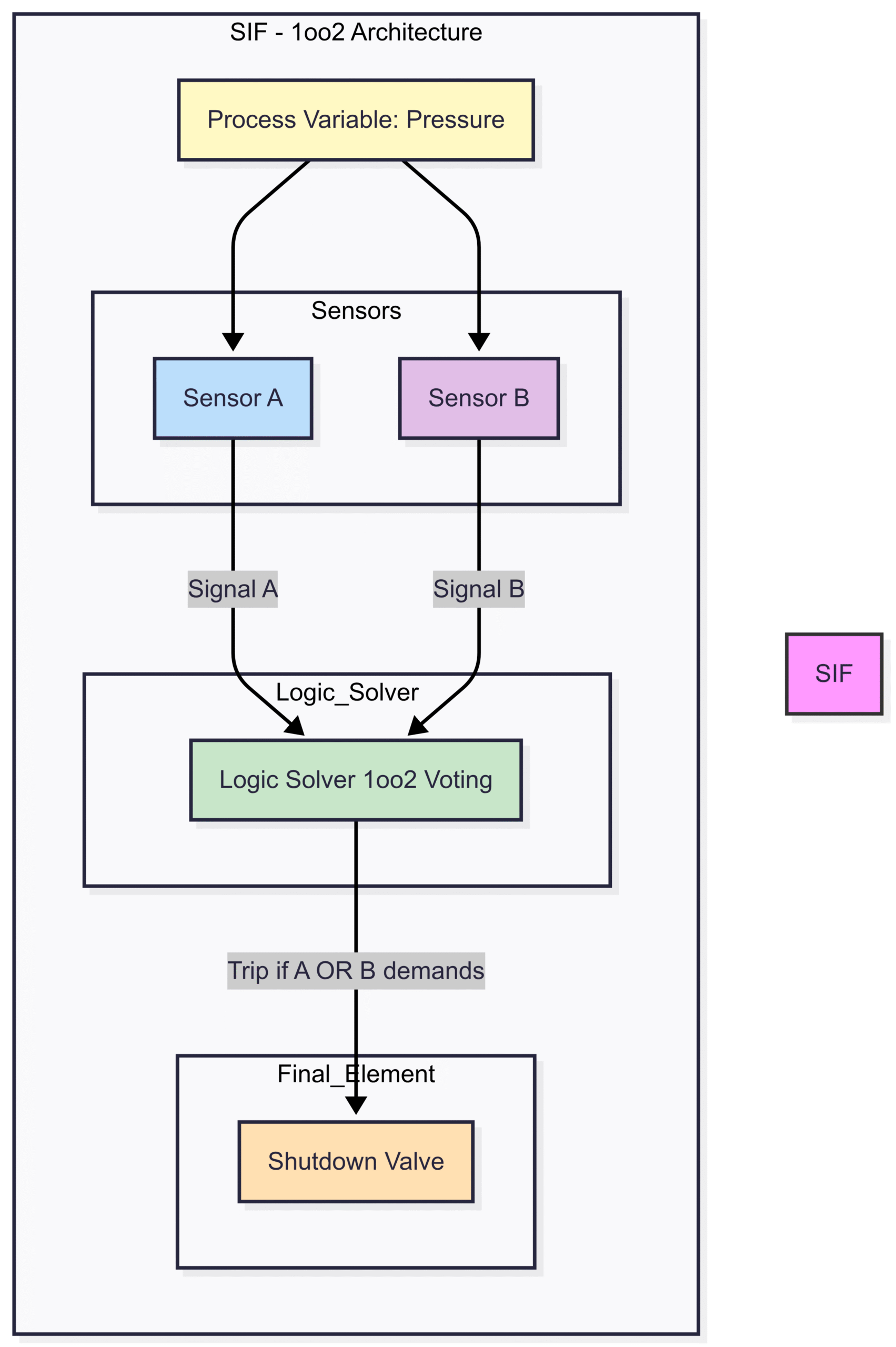
Imagine a high-pressure reactor that must be shut down if the pressure exceeds 100 bar. In a 1oo2 architecture, you would have two independent pressure transmitters (Sensor A and Sensor B) monitoring the reactor.
-
Normal Operation: Both Sensor A and Sensor B read below 100 bar. The logic solver receives two “OK” signals and keeps the shutdown valve open.
-
Hazardous Condition: The pressure rises to 105 bar. Both Sensor A and Sensor B detect this and send a “TRIP” signal to the logic solver. The solver sees at least one trip signal and immediately closes the shutdown valve.
-
Single Sensor Failure (Dangerous): Let’s say Sensor A fails in a way that it can’t detect the high pressure (a dangerous undetected failure). When the pressure rises to 105 bar, Sensor B still detects it and sends a “TRIP” signal. Because only one channel is needed to vote for a trip, the logic solver still closes the valve. The system remains safe despite a single fault. This is the primary advantage of 1oo2.
This operational principle can be visualized with the following diagram:
Key Characteristics of 1oo2
Hardware Fault Tolerance (HFT)
As per IEC 61511, the 1oo2 architecture has an HFT of 1. This means it can tolerate one dangerous hardware fault and still perform its safety function. This is a significant improvement over a 1oo1 system (HFT=0) and is often a minimum requirement for achieving SIL 2 or SIL 3.
Diagnostic Coverage (DC)
A critical feature of redundant architectures is diagnostics. The logic solver continuously compares the inputs from the two channels. If Sensor A reads 50 bar while Sensor B reads 80 bar, this discrepancy indicates a fault in one of the channels. The system can then raise an alarm for maintenance to investigate. This ability to detect faults is known as Diagnostic Coverage (DC). High DC is crucial because it allows faults to be repaired before a real demand occurs, significantly improving the system’s average probability of failure.
Spurious Trip Rate (STR)
The biggest drawback of the 1oo2 architecture is its impact on plant availability. Because either channel can initiate a trip, a single safe failure in any one channel will cause an unnecessary shutdown. For example, if Sensor A’s power supply fails, it might send a “TRIP” signal to the logic solver even though the process is perfectly safe. This is called a spurious or nuisance trip.
The Spurious Trip Rate (STR) of a 1oo2 system is roughly double that of a single 1oo1 system because there are twice as many components that can fail safe and cause a trip.
Pros and Cons of 1oo2 Architecture
Pros  |
Cons  |
| Excellent Safety: Significantly lower probability of failure on demand (PFDavg) compared to 1oo1. | Poor Availability: Higher probability of spurious (nuisance) trips. |
| High HFT: Achieves HFT=1, a common requirement for SIL 2/3. | Increased Cost: Requires double the number of sensors and input channels. |
| Good Diagnostics: The two channels can be compared to detect faults. | Increased Complexity: More complex wiring, programming, and maintenance. |
| Conceptually Simple: The “either/or” logic is easy to understand. | Potential for Common Cause Failures: Still vulnerable if both channels fail simultaneously due to a single external event. |
Calculating PFDavg for a 1oo2 System 
The performance of a SIF is measured by its Average Probability of Failure on Demand (PFDavg). This value represents the likelihood that the SIF will fail to perform its function when a real demand occurs. To claim a certain SIL, the calculated PFDavg for the entire SIF (sensors, logic solver, and final elements) must fall within the specified range.
The formula for the PFDavg of a 1oo2 architecture is more complex than for a 1oo1 system because it must account for redundancy and potential common cause failures.
Key Variables in PFDavg Calculation
-
: The rate of Dangerous Undetected failures. These are the most critical faults as they are hidden from diagnostics.
-
: The rate of Dangerous Detected failures. These are faults that are detected by diagnostics.
-
: The Test Interval or Proof Test Interval. The time between full functional tests of the SIF.
-
: The Mean Time To Repair. The average time it takes to repair a detected fault.
-
: The Common Cause Failure (CCF) Beta Factor. This represents the fraction of failures that will affect more than one channel due to a single common cause (e.g., miscalibration, flooding, power surge).
Simplified PFDavg Formula for 1oo2
Assuming perfect diagnostics and no common cause failures (an ideal but unrealistic scenario), the PFDavg is a function of the two channels failing simultaneously due to random, independent failures.
This simplified formula shows the power of redundancy. Because the failure rate (λ) is squared, the resulting PFDavg is significantly lower than that of a single channel
().
A More Complete PFDavg Formula (as per IEC 61511)
A more realistic calculation must account for common cause failures and the impact of detected failures. A widely used formula is:
This formula can be visualized as the sum of three main contributors to failure:
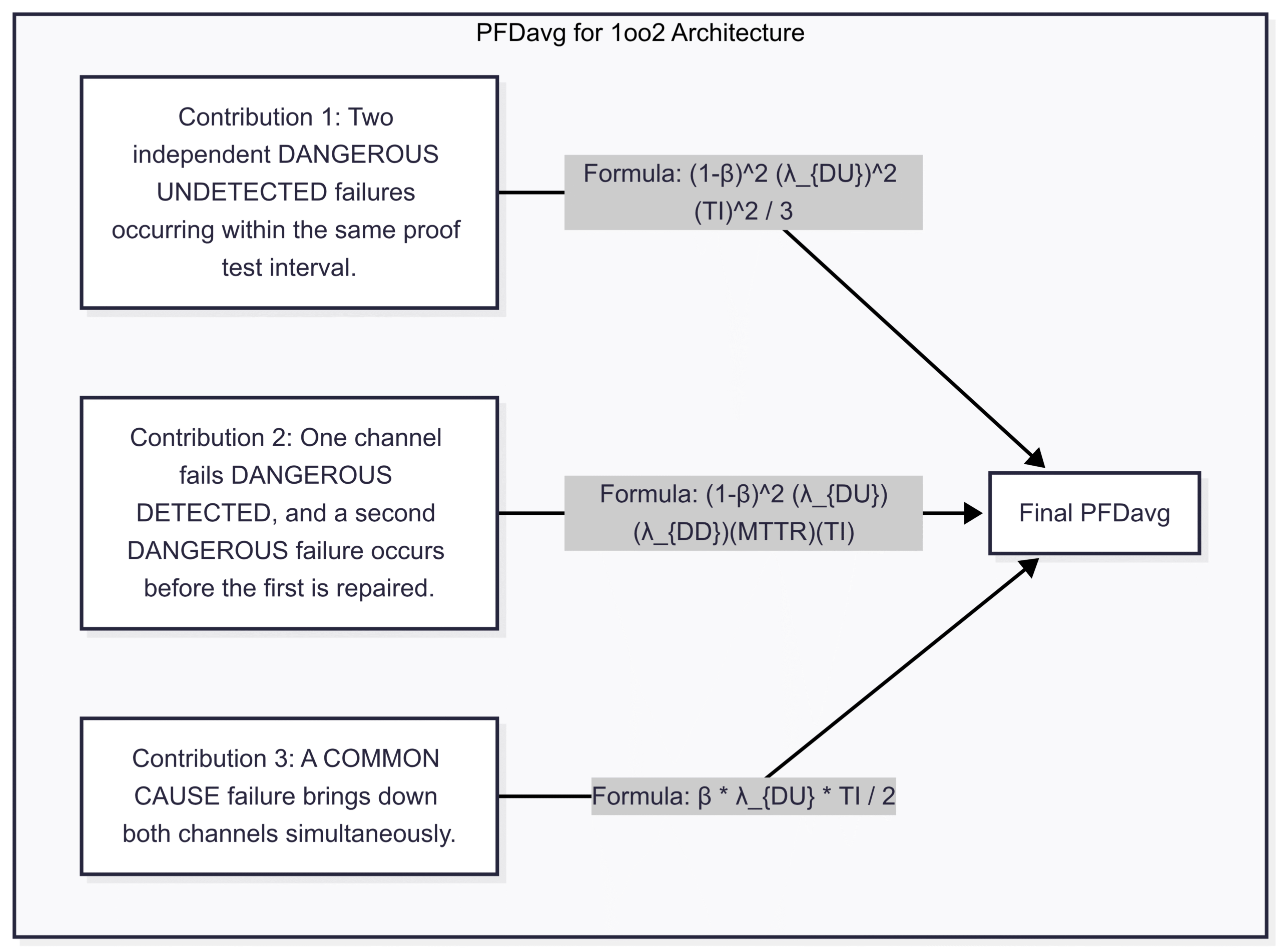
Note: The formulas in the diagram represent a common interpretation. Specific formulas can vary based on assumptions.The key takeaway is that Common Cause Failures (CCF), represented by the factor, often become the dominant term in the equation. No matter how much redundancy you add, if a single event can defeat both channels, your safety is compromised. Minimizing CCF through physical separation, diverse equipment suppliers, and robust maintenance procedures is paramount in 1oo2 systems.
Practical Implementation and Considerations
Choosing a 1oo2 architecture isn’t just a design decision; it has significant lifecycle implications.
Application Examples
The 1oo2 architecture is best suited for applications where safety is far more important than avoiding a spurious trip.
-
High-Pressure Reactor Protection: The consequence of failure (an explosion) is catastrophic, while the cost of a spurious shutdown, while high, is acceptable.
-
Burner Management Systems (BMS): Preventing furnace explosions by shutting off fuel on flame loss is a classic 1oo2 application. The risk of explosion far outweighs the cost of a nuisance trip.
-
Emergency Shutdown (ESD) Systems: Overall plant or unit-level ESD systems that protect against major hazards often use 1oo2 (or 2oo3) architectures for their sensors.
Maintenance and Testing Challenges
-
Proof Testing: According to IEC 61511, every SIF must be periodically proof tested to reveal any undetected dangerous failures. Testing a 1oo2 system is more complex than a 1oo1 system. Typically, one channel is taken offline and put into a bypass mode for testing while the other remains active, leaving the SIF in a temporary 1oo1 configuration. This procedure must be managed carefully to avoid introducing risk.
-
Bypass Management: The ability to bypass a channel for maintenance is essential, but it must be tightly controlled. An unauthorized or forgotten bypass negates the redundancy and compromises the entire SIF.
-
Sensor and Actuator Selection: To mitigate common cause failures, it’s good practice to use diverse technology or suppliers for the two channels where feasible. For example, using a pressure transmitter from one manufacturer and a pressure switch from another.
1oo2 vs. Other Architectures: A Comparative Look
The primary competitor to the 1oo2 architecture is the 2oo3 architecture, which offers a different balance of safety and availability. Let’s compare them.
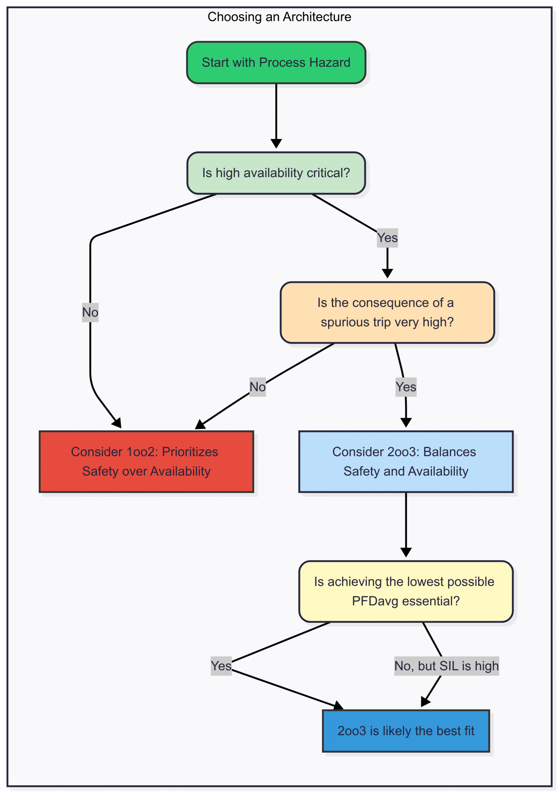
The 2oo3 architecture is often seen as the "gold standard" as it provides both high safety and high availability. However, this comes at the cost of significantly higher capital and maintenance expenditure. The 1oo2 architecture remains a highly effective and more economical solution for many applications where safety is the undisputed primary driver.
Conclusion: The Right Tool for the Right Safety Job
The 1oo2 safety architecture is a vital tool in the functional safety engineer’s arsenal. By using redundant channels with “OR” voting logic, it provides a substantial improvement in safety performance (lower PFDavg) over simpler 1oo1 systems, allowing designers to meet the stringent requirements of SIL 2 and SIL 3.
Its strength lies in its high hardware fault tolerance for dangerous failures, ensuring that a single component failure will not prevent the system from shutting down a process when a real demand arises. However, this safety comes at the price of lower operational availability, as a single safe component failure will lead to a nuisance trip.
As we’ve seen, the choice to implement a 1oo2 architecture must be a deliberate one, based on a thorough risk assessment and a clear understanding of the trade-offs between safety, availability, and cost. When applied correctly within the robust framework of IEC 61511, the 1oo2 architecture serves as a powerful and reliable guardian, protecting critical processes and ensuring safety remains the top priority.