What is a PLC? A Simple Explanation for Beginners
Have you ever wondered how a car is assembled with perfect precision, a beverage is bottled and capped in seconds, or an elevator knows exactly which floor to go to? The unsung hero behind these and countless other automated tasks is a powerful little box known as a Programmable Logic Controller, or PLC.
If you’re new to the world of automation, engineering, or manufacturing, the term “PLC” might sound intimidating. But the core concept is surprisingly simple. A PLC is essentially a specialized, heavy-duty computer designed to thrive in harsh industrial environments and control machinery with incredible reliability. It’s the digital brain that replaced complex, failure-prone systems of electrical relays, timers, and sequencers, revolutionizing modern industry.
This guide will break down everything you need to know about PLCs in simple, easy-to-understand terms. We’ll explore what they are, how they work, their key components, and where you can find them in the world around you.
How Does a PLC Work? The Scan Cycle
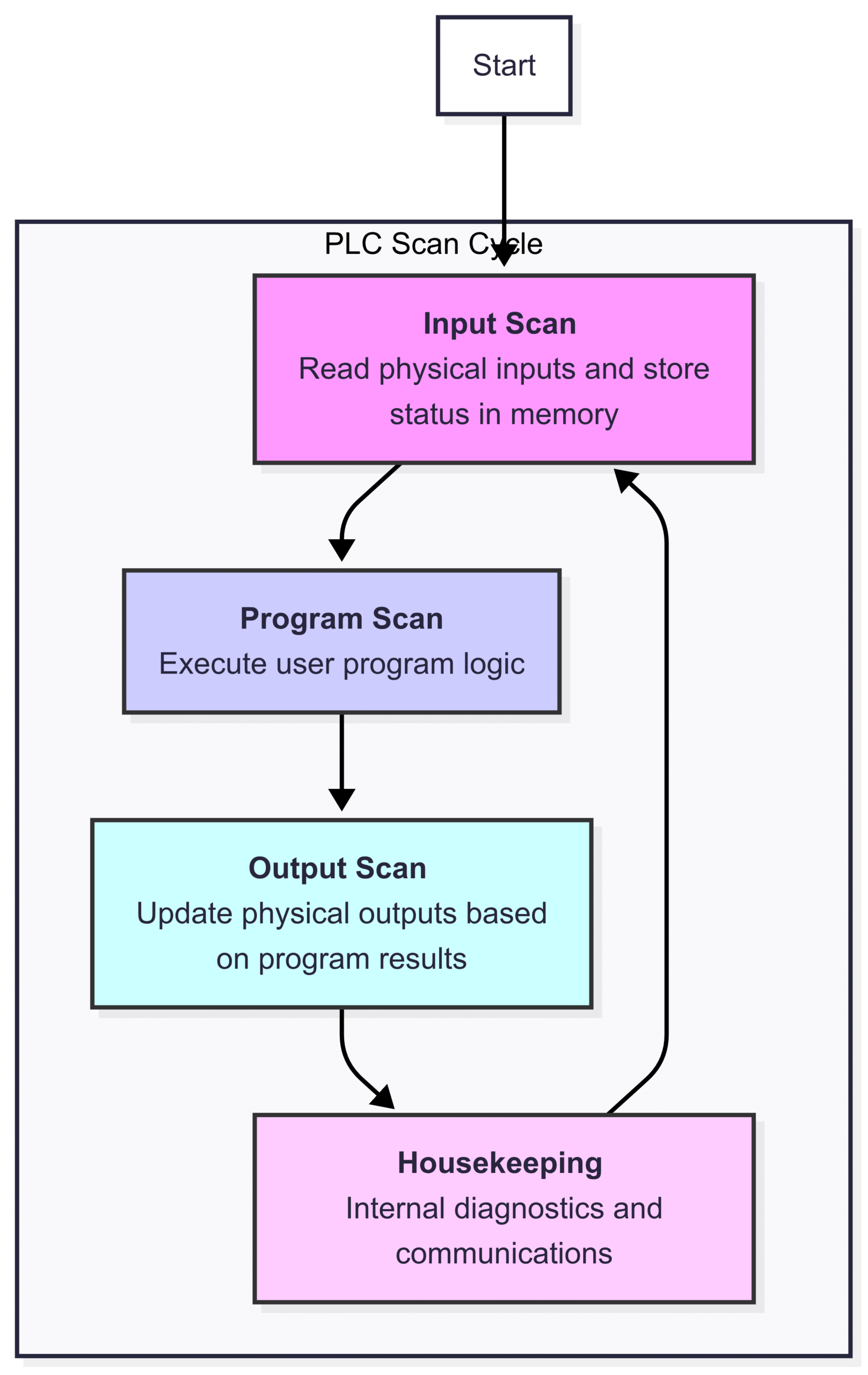
The magic of a PLC happens in a continuous, looping process called the scan cycle. This cycle runs incredibly fast, often many times per second, ensuring the PLC can react to changes in real-time. The scan cycle consists of four main steps:
Input Scan: The PLC checks the status of every input device connected to it. An input device could be a sensor detecting a product, a button pressed by an operator, or a switch indicating a door is closed. It takes a snapshot of all these input statuses and stores them in its memory.
Program Scan (or Logic Scan): This is where the “thinking” happens. The PLC’s central processing unit (CPU) executes the user-created program, one instruction at a time. The program is essentially a set of rules (e.g., “IF input button A is pressed AND sensor B is on, THEN turn on motor C”). The PLC uses the input statuses it just saved in memory to solve this logic.
Output Scan: After the program scan is complete, the PLC updates the status of all the output devices connected to it based on the results of the program. An output device could be a motor, a pump, a warning light, or a solenoid valve. If the program decided to turn on motor C, the PLC now sends the electrical signal to energize that motor.
Housekeeping (or Communication): In this final step, the PLC performs internal diagnostics to check its own health. It also handles any communication tasks, such as sending data to a control panel, a supervisory control and data acquisition (SCADA) system, or another PLC.
Once the housekeeping is done, the cycle immediately starts over again with the input scan. This continuous loop ensures the PLC is always monitoring its inputs and controlling its outputs according to the programmed logic.
Here’s a simple diagram illustrating the PLC scan cycle:
Key Components of a PLC
While PLCs come in various shapes and sizes—from small “brick” PLCs with a fixed number of inputs and outputs to large, modular rack-based systems—they all share the same fundamental components.

1. Central Processing Unit (CPU)
The CPU is the brain of the PLC. This microprocessor carries out all the computational tasks, including executing the program, managing memory, monitoring the inputs, and controlling the outputs. The speed of the CPU determines how quickly the PLC can complete its scan cycle, which is a critical factor in high-speed automation.
2. Power Supply
The power supply module takes the incoming line voltage (e.g., 120V AC or 240V AC) and converts it into the low-voltage DC power (typically 24V DC) that the CPU and other internal components need to operate. A reliable power supply is crucial for ensuring the PLC runs continuously without interruption, even with fluctuations in the main power source.
3. Memory (RAM & ROM)
The PLC has two main types of memory:
ROM (Read-Only Memory): This is where the PLC’s operating system firmware is permanently stored. This data is non-volatile, meaning it isn’t lost when power is turned off.
RAM (Random-Access Memory): This is the working memory used to store the user’s program, the status of all the inputs and outputs, and the values of timers, counters, and other data. Most modern PLCs use a battery or a supercapacitor to back up the RAM, so the user program isn’t lost during a power outage.
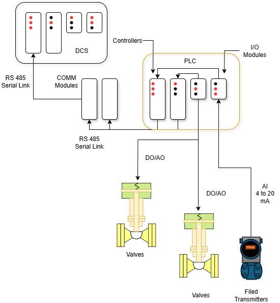
4. Input/Output (I/O) Modules
The I/O modules are the PLC’s connection to the physical world. They are the “senses” and “hands” of the system.
Input Modules: These modules detect signals from input devices like sensors, switches, and buttons. They convert these real-world electrical signals into the digital format that the CPU can understand. Inputs can be digital (on/off) or analog (a range of values, like temperature or pressure).
Output Modules: These modules take the digital signals from the CPU and convert them back into electrical signals that can control output devices like motors, solenoids, relays, and lights. Outputs can also be digital or analog.
5. Programming Device
This isn’t part of the PLC itself, but it’s essential for its operation. A programming device is a computer (usually a laptop) running special software provided by the PLC manufacturer (e.g., Rockwell’s RSLogix/Studio 5000, Siemens’ TIA Portal). Engineers and technicians use this device to write the control program, download it to the PLC’s memory, and monitor its operation for troubleshooting.
PLC vs. Other Controllers: Relays and Microcontrollers
To truly appreciate the power of a PLC, it helps to compare it to the technologies it replaced and other modern alternatives.
PLC vs. Relay Logic
Before PLCs, automation was achieved with complex panels of electromechanical relays, timers, and counters. A “program” was a physical wiring diagram.
Complexity: A simple change in logic required physically rewiring the entire panel, a time-consuming and error-prone process. With a PLC, you just edit a few lines of code on a laptop.
Reliability: Relays have moving parts that wear out over time, leading to failures. PLCs are solid-state devices with no moving parts, making them far more reliable and long-lasting.
Size: A PLC can replace hundreds of relays, dramatically reducing the physical size of the control cabinet.
Cost: While the initial cost of a single PLC might be higher than a few relays, for any reasonably complex system, the PLC is far more cost-effective due to reduced wiring, labor, and maintenance costs.
PLC vs. Microcontroller (e.g., Arduino, Raspberry Pi)
Microcontrollers are the tiny “computers on a chip” found in everything from microwaves to kids’ toys. While they are powerful, they are not designed for the same job as a PLC.
Ruggedness: PLCs are built to withstand the harsh conditions of a factory floor—extreme temperatures, electrical noise, vibrations, and humidity. A microcontroller board like an Arduino would quickly fail in such an environment.
Voltage and I/O: PLCs are designed to work directly with high-voltage industrial signals (like 24V DC or 120V AC). Microcontrollers work with low-voltage TTL logic (typically 3.3V or 5V) and require extensive additional circuitry to interface with industrial equipment safely.
Software and Standards: PLC programming languages (like Ladder Logic) are standardized and designed for industrial control logic. They are easy for electricians and technicians to learn and troubleshoot. Microcontroller programming (typically in C/C++ or Python) is more versatile but also more complex and less standardized for industrial applications.
Reliability and Safety: PLCs are designed for high reliability and often include safety-certified features. Their operating systems are real-time and extremely stable, which is critical when controlling dangerous machinery.
Programming a PLC: The Language of Logic
One of the most defining features of a PLC is its unique programming environment. While some PLCs can be programmed in text-based languages, the most common language by far is Ladder Logic (or Ladder Diagram – LD).
Ladder Logic (LD)
Ladder Logic was designed to mimic the appearance of the electrical relay wiring diagrams it replaced. This made it very easy for electricians and factory technicians, who were already familiar with relay schematics, to transition to programming PLCs.
A ladder logic program looks like a ladder with two vertical rails representing the power supply and horizontal “rungs” representing lines of logic.
Contacts (Inputs): On the left side of a rung, you have contacts that represent inputs or internal memory bits. A normally open contact
—| |—is “true” when the corresponding input is on. A normally closed contact—|/|—is “true” when the corresponding input is off.Coils (Outputs): On the right side of a rung, you have coils
—( )—that represent outputs or internal memory bits. If the combination of contacts on the left side of the rung creates a true logical path, the coil is energized, or turned “on.”
Beyond simple contacts and coils, ladder logic includes more advanced functions like:
Timers: Used to delay an action (e.g., wait 5 seconds after a box arrives before starting a conveyor).
Counters: Used to count events (e.g., turn on a light after 10 products have passed a sensor).
Math Instructions: For performing arithmetic operations.
Data Manipulation: For moving or comparing numerical values.
While Ladder Logic is the most common, the IEC 61131-3 standard defines five PLC programming languages:
Ladder Diagram (LD): Graphical
Function Block Diagram (FBD): Graphical
Structured Text (ST): Text-based (similar to Pascal)
Instruction List (IL): Text-based (similar to assembly language)
Sequential Function Chart (SFC): Graphical, for managing sequential processes
Where Are PLCs Used? Real-World Applications
PLCs are the backbone of automation in nearly every industry. If a process is repetitive, requires high precision, or needs to be controlled automatically, there’s a good chance a PLC is involved.
Manufacturing: This is the classic home of the PLC. They control assembly lines, robotic arms, CNC machines, packaging and labeling machines, and quality control inspection systems.
Food & Beverage: PLCs manage mixing, cooking, bottling, and packaging processes, ensuring consistency and adherence to recipes. Think of breweries, bakeries, and dairy processing plants.
Automotive: The automotive industry is a massive user of PLCs. They control everything from the stamping of body panels and the welding by robots to the final assembly and painting processes.
Energy & Utilities: PLCs control water treatment plants, power distribution grids, and oil and gas pumping stations. They manage flow rates, pressures, and temperatures to ensure safe and efficient operation.
Pharmaceuticals: In drug manufacturing, precision is paramount. PLCs control the precise mixing of ingredients, manage batch processes, and ensure sterile environments.
Building Automation: Modern buildings use PLCs (or similar controllers called DDCs) to manage HVAC (heating, ventilation, and air conditioning), lighting systems, elevators, and security systems for maximum energy efficiency and comfort.
Entertainment: Yes, even theme parks use PLCs! They control the motion of rides, animatronics, and special effects, ensuring a thrilling but safe experience for guests.
The Future of PLCs
The PLC is here to stay, but it’s also evolving. Modern PLCs, sometimes called Programmable Automation Controllers (PACs), are becoming more powerful than ever. They feature faster processors, more memory, and enhanced communication capabilities. They are at the heart of the “Industrial Internet of Things” (IIoT) and Industry 4.0, collecting vast amounts of data, communicating over Ethernet and wireless networks, and integrating seamlessly with cloud-based systems for analytics and remote monitoring.
Conclusion: The Powerful Brain of Modern Industry
The Programmable Logic Controller is a remarkable piece of technology. Born from a need to simplify and improve upon complex relay panels, it has become the robust, reliable, and flexible brain behind the automated world we live in. From the car you drive to the food you eat, the PLC works silently in the background, executing its logic with tireless precision. Understanding the basic principles of the PLC—its scan cycle, core components, and programming logic—is the first step into the fascinating and ever-expanding world of industrial automation.