The 250-Ohm Mystery: Why It Is the Heart of the 4-20 mA Loop
If you have spent any time in the field of industrial instrumentation, you have likely carried a 250-ohm resistor in your pocket or seen one installed across the terminals of a PLC analog input card. It is the unsung hero of the process control world.
But why 250 ohms? Why not 100? Why not 1000?
While it might seem like an arbitrary convention, the choice of 250 ohms is mathematically precise, electrically efficient, and critical for digital communication protocols like HART. This guide will dismantle the 4-20 mA loop and explain exactly why this specific component is the bridge between the analog and digital worlds.
1. The Problem: Current vs. Voltage
To understand the solution, we must first understand the problem. Industrial transmitters (pressure, temperature, flow, level) transmit data using current (4-20 mA), but most control systems (DCS, PLC, or SCADA) process data using voltage.
Why Transmitters Use Current
Current is preferred for field transmission because it is immune to voltage drops caused by long wire lengths. According to Kirchhoff’s Current Law, the current entering a loop is equal to the current leaving it. If a transmitter sends 12 mA, the receiver gets 12 mA, regardless of whether the wire is 10 meters or 1000 meters long (provided the power supply voltage is sufficient to drive the loop).
Why Controllers Read Voltage
Microprocessors and Analog-to-Digital Converters (ADCs) inside your PLC or DCS generally operate on voltage signals (typically 0-5V DC or 0-10V DC). They measure potential difference, not current flow.
The Bridge: To get the current signal from the field into the voltage-reading processor of the controller, we need a conversion mechanism. This is where Ohm’s Law comes in.
Where:
V = Voltage (Volts)
I = Current (Amperes)
R = Resistance (Ohms)
We need a resistor that converts the industrial standard current range (4-20 mA) into a standard voltage range that the controller can utilize.
2. The Mathematics of 250 Ohms
Let’s run the math to see why 250 ohms.
Scenario A: Converting to 1-5 Volts
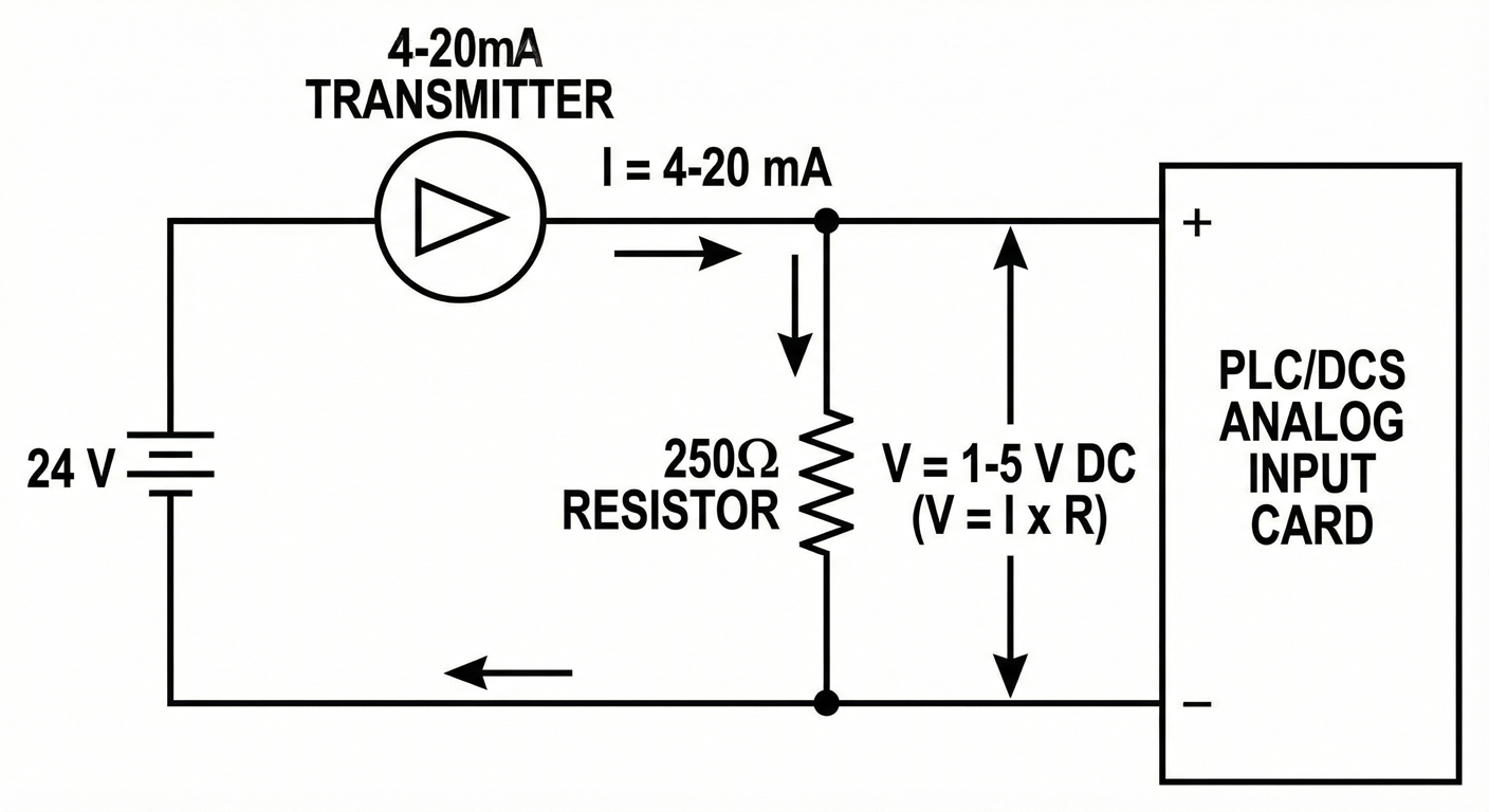
The most common standard for internal A/D conversion in industrial controllers is 1 to 5 Volts DC. Let’s see what happens when we apply the 4-20 mA signal to a 250-ohm resistor.
At Minimum Signal (4 mA):
At Maximum Signal (20 mA):
By using a 250Ω resistor, we map the 4-20 mA signal perfectly to a 1-5 V signal.
0% Process Variable = 4 mA = 1 V
100% Process Variable = 20 mA = 5 V
This 1-5V range provides a “Live Zero.” If the voltage drops to 0V, the controller knows the wire is broken (since even the minimum process value should produce 1V).
Why Not Other Resistor Values?
If we used 500 Ohms:
0.020 A x 500Ω = 10 V.
This creates a 2-10V signal. While some controllers accept 0-10V, many standard ADCs are optimized for 5V logic. Furthermore, dropping 10V across the resistor leaves less voltage available for the transmitter (voltage headroom), potentially starving the device of power.
If we used 100 Ohms:
0.020A times 100Ω = 2 V.
The signal range would be 0.4V to 2V. This is a very small range, which reduces the resolution of the measurement. The signal-to-noise ratio would worsen, making the reading more susceptible to electrical interference.
3. The Critical Role in HART Communication
While the voltage conversion is the primary reason for the resistor, the HART (Highway Addressable Remote Transducer) protocol is the reason the resistor is strictly required for configuration and diagnostics.
HART imposes a digital communication signal on top of the analog 4-20 mA wave. It does this by Frequency Shift Keying (FSK)—modulating a sine wave of ±0.5 mA at 1200 Hz (Logic 1) and 2200 Hz (Logic 0).
The Impedance Requirement
For a HART communicator (handheld field device) to “talk” to the transmitter, there must be a minimum impedance in the loop.
If you connect a HART communicator directly across a power supply with very low internal impedance, the power supply acts as a “short circuit” to the high-frequency HART AC signal. It absorbs the signal, and the communicator displays the dreaded “No Device Found” error.
The Solution:
The HART protocol specifications require a loop impedance of at least 230 Ohms.
The 250-ohm resistor provides this necessary impedance.
It isolates the AC HART signal from the low-impedance power supply, allowing the communicator to read the voltage pulses across the loop.
Therefore, even if your controller could technically read current without a resistor, you still need the 250-ohm resistor in the loop if you ever plan to connect a HART communicator to configure the device.
4. Hardware Selection: It’s Not Just Any Resistor
You cannot simply grab a carbon-film resistor from a hobby kit and shove it into a safety-critical industrial panel. The selection of the 250-ohm resistor requires engineering consideration.
A. Precision (Tolerance)
In instrumentation, accuracy is money.
Standard resistors have a tolerance of ±5% or ±10%.
If your 250-ohm resistor is actually 262 ohms (+5%), your 20 mA signal will read as 5.24 Volts.
Your DCS will interpret this as 106% of the process range.
Requirement: Always use precision resistors with a tolerance of ±0.1% or better. This ensures that 20 mA translates exactly to 5.00 V.
B. Power Rating (Wattage)
We must ensure the resistor can handle the heat generated by the current.
Using the Power Formula:
P = I^2 x R
At maximum loop current (let’s assume a fault condition of 24 mA to be safe):
A standard 1/4 Watt (0.25 W) resistor is sufficient, as 0.144 W is well below the limit. However, for robustness and longevity, many engineers prefer 1/2 Watt (0.5 W) precision resistors to ensure cool operation inside hot control panels.
C. Temperature Coefficient
Resistors change their resistance as they heat up. In a control cabinet that might fluctuate between 20°C and 50°C, a cheap resistor will drift, causing your process variable to drift.
Requirement: Use metal film resistors with a low temperature coefficient (approx. 25 ppm/°C or lower).
5. Where to Install the Resistor?
The physical location of the resistor depends on your specific hardware setup, but there are generally two configurations.
1. Internal to the AI Card
Many modern PLC/DCS Analog Input cards have the 250-ohm resistor built-in.
Configuration: You simply wire the + and – loop wires to the card.
Note: You often need to set dip-switches on the card to “Current Mode” (which engages the internal resistor) vs. “Voltage Mode” (which bypasses it).
2. External Terminal Block
For older cards or generic voltage input cards, the resistor is installed externally.
Location: Usually on the terminal strip in the marshalling cabinet.
Wiring: The resistor is screwed into the terminals in parallel with the voltage input channels. The 4-20 mA wires land on the same terminals.
Warning: Never install the resistor at the field device end (the transmitter) if you are reading voltage at the control room. This would create a voltage drop at the field, but the voltage would drop further along the long wire run back to the control room, leading to errors. The conversion from Current to Voltage must happen as close to the ADC (Controller) as possible.
6. Summary
The 250-ohm resistor is not a random choice. It is the linchpin of analog signal processing because:
Mathematical Harmony: It perfectly converts 4-20 mA into the standard 1-5 VDC required by ADCs.
HART Compliance: It provides the minimum impedance (230Ω+) required for digital HART signals to exist on the loop.
Signal Integrity: It maintains a high enough voltage for good resolution while leaving enough headroom for the transmitter to operate.
Next time you see that small, striped component on a terminal block, you’ll know it’s doing the heavy lifting of translating the physical world into the digital one.
Check Your Understanding
Q: Can I use two 500-ohm resistors in parallel if I don’t have a 250-ohm one?
A: Yes. Two 500Ω resistors in parallel create an equivalent resistance of 250Ω. This is a common field trick.
Q: What happens if the resistor fails open?
A: The loop opens, current falls to 0 mA, and the controller reads 0V (indicating a wire break/fault).