

Mastering the Flow: A Comprehensive Guide for Instrument Engineer on Reviewing Orifice Plate Sizing Calculations
In the intricate world of Engineering, Procurement, and Construction (EPC) for industrial plants, precision is not just a goal; it’s a fundamental requirement. From chemical reactors to hydrocarbon pipelines, the ability to accurately measure and control fluid flow is paramount for safety, efficiency, and quality. At the heart of this measurement lies one of the most common yet critically important devices: the orifice plate flow meter.
While the orifice plate itself is a simple, robust piece of metal, the calculations that determine its exact specifications are complex. As an EPC contractor, you receive these sizing calculations from instrument manufacturers or vendors. Your responsibility doesn’t end at procurement. A meticulous review and validation of these documents are crucial to prevent costly operational issues, startup delays, and even safety hazards down the line.
This guide provides a definitive framework for EPC engineers—whether in instrumentation, process, or piping—on how to conduct a thorough review of a vendor’s orifice plate sizing calculation. We’ll delve into everything from fundamental input data to the nuances of beta ratio (β), straight-length requirements, and mechanical thickness, ensuring your project’s flow measurement systems are built on a foundation of accuracy.
Assembling the Essential Documentation:
Before you can even begin the review, you must have the correct documentation at your fingertips. A calculation sheet in isolation is meaningless. The review process is one of cross-referencing and verification.
Here’s the typical flow of documents and the review cycle:
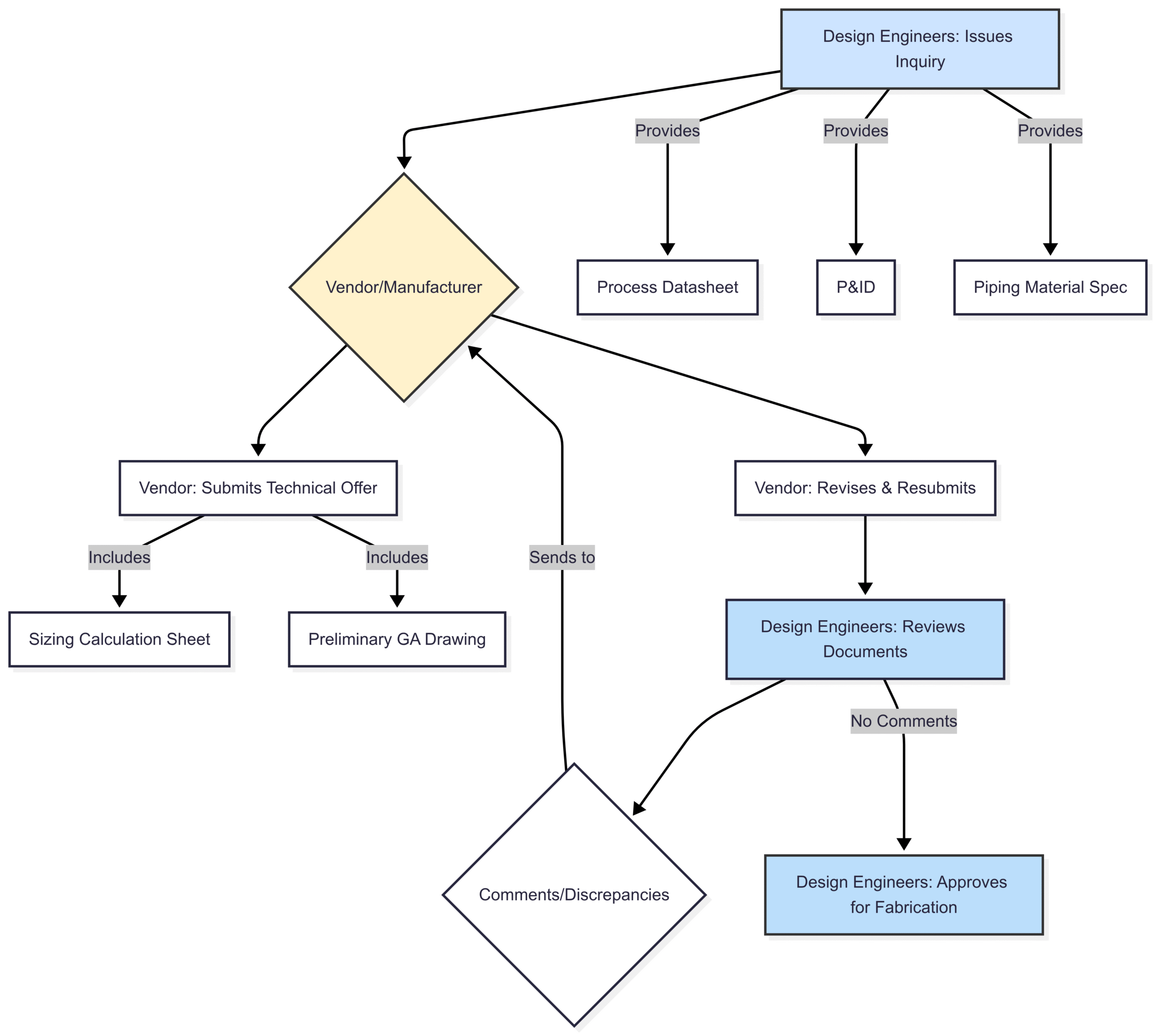
Ensure you have the following documents from your internal project team and the vendor:
Process Datasheet (PDS): This is your source of truth. It is prepared by the EPC’s process department and contains all the fluid properties and operating conditions.
Piping and Instrumentation Diagram (P&ID): This shows the location of the orifice plate in the larger process, including adjacent fittings like valves, elbows, and reducers.
Vendor’s Orifice Plate Sizing Calculation Sheet: The primary document under review.
Vendor’s General Arrangement (GA) Drawing: This shows the physical dimensions of the orifice flange assembly.
Piping Material Specification (PMS): Defines the approved materials for the pipe, flange, plate, and gaskets for that specific service.
With these documents in hand, you can begin the systematic review.
Section 1: Decoding the Sizing Calculation Sheet – Input Data Verification
The most common source of error is incorrect input data. The principle of “Garbage In, Garbage Out” applies perfectly here. The first and most critical step is to compare every input on the vendor’s calculation sheet against your project’s PDS.
Key Input Parameters to Verify:
Fluid Name and State: Does it match? (e.g., “Natural Gas,” “Demineralized Water”). Is the state correct (Liquid, Gas, Steam)?
Operating Conditions (Min, Normal, Max Flow): This is the most crucial check.
Flow Rate: Ensure the units (e.g.,
kg/h,Sm³/d,gpm) are consistent and the values for minimum, normal, and maximum operating cases match the PDS.Operating Pressure: Verify the upstream pressure (
P_1) at each flow case.Operating Temperature: Verify the temperature (
T_1) at each flow case.
Fluid Properties at Operating Conditions: These properties can change significantly with pressure and temperature.
Density (ρ): Check the density for each flow case. For liquids, it’s relatively stable; for gases, it’s highly dependent on P & T.
Viscosity (
mu): Dynamic or kinematic viscosity must match the PDS.Isentropic Exponent (
korgamma (γ)): For gases and steam, this value (ratio of specific heats,C_p/C_v) is critical for calculating the expansibility factor.
Pipe Details:
Nominal Pipe Size (NPS) and Schedule (SCH): This must match the P&ID and PMS.
Pipe Internal Diameter (ID): The vendor must use the exact internal diameter (
D) corresponding to the NPS and schedule, as specified in standards like ASME B36.10M. A common error is using a generic or nominal ID. Even a small deviation here significantly impacts the calculation.Pipe Material: Cross-check with the PMS.
Pro Tip: Create a checklist. Print both the PDS and the vendor’s calculation sheet. Use a highlighter to mark each verified value. This methodical approach prevents accidental oversight.
Section 2: The Heart of the Calculation:
Once the inputs are confirmed, you can move on to the calculated outputs. These parameters determine the performance and suitability of the orifice plate for the application.
2.1 The All-Important Beta Ratio (β)
The Beta Ratio is the single most important parameter in an orifice plate design. It is the ratio of the orifice bore diameter (d) to the pipe’s internal diameter (D).
The value of β is a trade-off between measurement accuracy and pressure loss.
Low β (e.g., 0.2-0.4):
Pros: High differential pressure (Δp) for a given flow rate, making it easy for transmitters to read. Good for low-flow applications.
Cons: High permanent pressure loss (PPL), which means higher energy consumption for pumps or compressors. Higher noise levels.
High β (e.g., 0.6-0.75):
Pros: Low permanent pressure loss, saving energy.
Cons: Low Δp
, which can be difficult to measure accurately, especially at lower flow rates (turndown). Higher uncertainty in the discharge coefficient. More sensitive to upstream flow disturbances.
Review Checklist for β:
Is it within the standard range? The cornerstone standard, ISO 5167, specifies that the Beta Ratio (β) must be between 0.10 and 0.75. For best practice and lower uncertainty, most companies specify a design range of 0.20 to 0.70.
Is it too high or too low? A β value of 0.74 might be technically compliant with ISO 5167, but it’s a red flag. It suggests the orifice is struggling to generate enough Δp, or the line size might be too small for the maximum flow rate. Conversely, a β of 0.15 might create an unacceptably high permanent pressure loss.
Does it provide a reasonable turndown? The turndown ratio is the ratio of maximum to minimum flow that can be measured accurately. Check the Δp at minimum flow. If it’s too low (e.g., less than 10% of the transmitter’s upper range value), the measurement will be unreliable.
2.2 Differential Pressure (Δp) and Permanent Pressure Loss (PPL)
Differential Pressure (Δp): This is the “signal” generated by the orifice plate that the differential pressure transmitter measures.
Review Check: The calculated Δp at the maximum flow rate should ideally be close to, but not exceeding, the upper range of the selected DP transmitter. Standard transmitter ranges are often 0-2500, 0-5000, or 0-10000 mmWC (millimeters of water column). If the calculated Δp at max flow is, for example, 2600 mmWC, the vendor should either adjust the β
or a transmitter with a higher range must be selected.
Permanent Pressure Loss (PPL): This is the unrecoverable energy loss inflicted on the process fluid, which translates to pump or compressor energy costs over the plant’s lifetime.
Review Check: The PPL is often expressed as a percentage of the Δp. It is highly dependent on the β Ratio (
PPL ≈ (1 - \β^2) * Δp). The process datasheet (PDS) often specifies a maximum allowable PPL. Ensure the calculated value does not exceed this limit.
2.3 Reynolds Number (Re)
The Reynolds Number is a dimensionless quantity that describes the flow regime (laminar or turbulent). Orifice plate calculations are only valid for turbulent flow.
Review Check: ISO 5167 and other standards (like AGA 3) specify minimum
Revalues for the validity of their discharge coefficient equations. This limit depends on the β Ratio. Typically,Remust be greater than 5000 for the given β and pipe size. Ensure theRecalculated at the minimum flow rate is above this validity threshold. If it’s not, the measurement will be inaccurate at the low end of its operating range.
2.4 Discharge Coefficient (C_d) and Expansibility Factor (ε)
Discharge Coefficient (
C_d): This is an empirical factor that corrects for the difference between the theoretical and actual flow rate due to energy losses and flow contraction. Its value is calculated using a complex empirical equation, most commonly the Reader-Harris/Gallagher (1998) equation as specified in ISO 5167.Review Check: You don’t need to recalculate this by hand. However, you should verify that the vendor has stated which equation they used (e.g., “Reader-Harris/Gallagher per ISO 5167”). The value of
C_dis typically in the range of 0.60 to 0.62.
Expansibility (or Expansion) Factor (ε): This factor is only applicable for compressible fluids (gases, steam). It accounts for the change in fluid density as it passes through the high-velocity, low-pressure orifice bore.
Review Check: For liquids, ε must be 1.0. For gases, verify it has been calculated. The value will always be less than 1.0. Ignoring this factor for a gas flow meter will result in a significant over-reading of the flow rate.
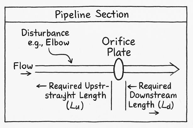
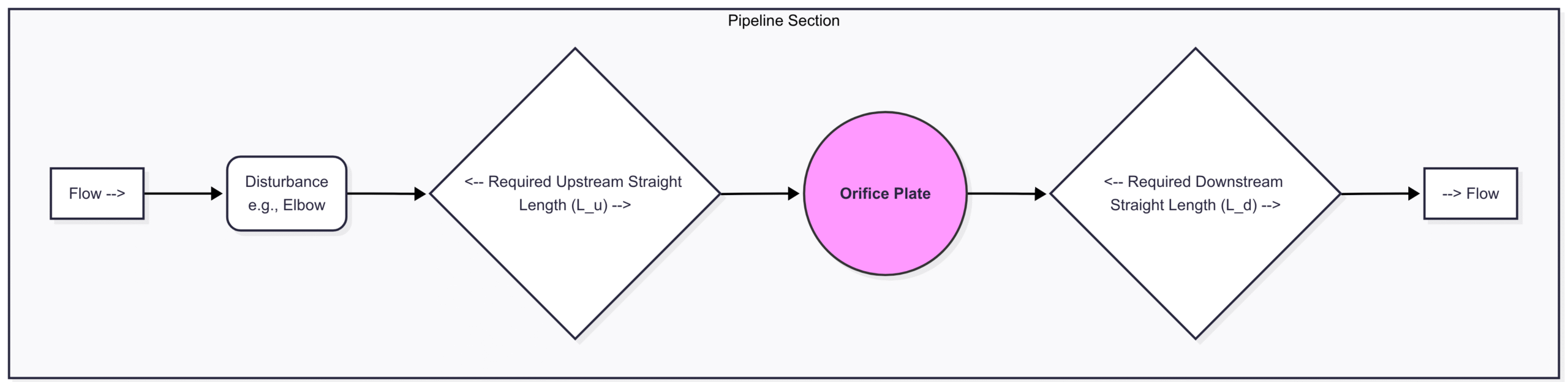
Section 3: The Critical Installation Requirement – Upstream and Downstream Straight Lengths
An orifice plate will only provide an accurate measurement if the fluid flow profile is uniform and fully developed as it approaches the plate. Any disturbances upstream (like elbows, valves, reducers) will swirl the flow and distort this profile, leading to large, unquantifiable errors.
To mitigate this, standards demand a minimum length of straight, unobstructed pipe both upstream and downstream of the orifice assembly.
Review Checklist for Straight Lengths:
Identify Upstream Disturbances: Look at your P&ID. What is immediately upstream of the orifice flange tappings? Is it a single 90° elbow? Two elbows in the same plane? Two elbows in different planes? A gate valve? A reducer?
Consult the Standard (ISO 5167-2): This standard provides tables that specify the required straight lengths for various types of fittings and different Beta Ratios.
Example: For a single 90° elbow upstream and a β
of 0.70, ISO 5167 requires 36 pipe diameters (36D) of straight pipe. However, for a βof 0.20, it only requires 10D. This highlights how a lower Beta Ratio can be more forgiving of installation effects.
Compare Required vs. Actual: Check the vendor’s calculation sheet. They should state the required upstream and downstream lengths based on their calculated β
. Now, look at the P&ID and the physical piping layout drawings. Is that required length actually available in the design?The “0.5 Beta” Rule of Thumb: If the P&ID shows a flow conditioner is installed, or if the tables indicate “zero additional uncertainty,” the required lengths may be shorter. A common requirement for this condition is that the Beta Ratio must be less than 0.5. Check if the vendor’s calculation adheres to this if they claim reduced straight lengths.
Downstream Length: Don’t forget the downstream requirement. It’s typically shorter (e.g., 4D to 8D) but equally important for pressure recovery and measurement stability.
If the available straight length in your design is less than what the vendor’s calculation requires, you have a major problem. The options are:
Modify the piping layout (expensive and often impossible late in a project).
Instruct the vendor to resize the orifice with a smaller β to reduce the straight length requirement.
Incorporate a flow conditioner (adds cost and pressure drop).
Section 4: Mechanical Integrity – Thickness, Materials, and Final Checks
A sizing calculation is not just about flow dynamics; it’s also about ensuring the physical plate can withstand the process conditions.
4.1 Orifice Plate Thickness Calculation
The orifice plate is subjected to the full differential pressure, which creates a significant force trying to bend or “dish” it. A bent plate will have a larger effective bore, leading to under-reading of the flow rate.
Review Check: The vendor must perform a thickness calculation based on standards like ASME MFC-3M or ISO 5167-2. This calculation considers:
The maximum possible differential pressure (often the full range of the DP transmitter).
The orifice bore diameter (
d).The allowable stress of the plate material at the design temperature.
The calculation should result in a minimum required thickness. The vendor’s selected plate thickness on the GA drawing must be greater than or equal to this calculated minimum. A common standard thickness is 3 mm (1/8″) or 6 mm (1/4″), but this must always be verified by calculation.
4.2 Material Selection and Gaskets
Review Check: Cross-reference the materials listed on the calculation sheet and GA drawing with your project’s Piping Material Specification (PMS).
Plate Material: Typically 316 Stainless Steel, but can be Monel, Hastelloy, Duplex, etc., for corrosive or high-temperature services.
Flange Material: Must match the connecting pipe (e.g., ASTM A105 for carbon steel, A182 F316 for stainless steel).
Gasket Material: Must be compatible with the fluid and temperature. Spiral wound gaskets are common.
4.3 Vent and Drain Holes
For Gas/Steam Service: A small vent hole is often drilled at the bottom of the plate to allow any condensed liquid to pass, preventing buildup.
For Liquid Service: A small drain hole is drilled at the top of the plate to allow any entrained gas or vapor to pass.
Review Check:
Does the P&ID or PDS require a vent/drain hole?
Is it correctly specified on the vendor’s drawing (vent at bottom, drain at top)?
The hole itself introduces a small error. The calculation software should account for this, but as a reviewer, ensure its presence is noted. The diameter of the hole must not exceed a certain percentage of the bore diameter as defined by the standards.
Conclusion: An Instrument Engineer Role as the Final Gatekeeper
Reviewing an orifice plate sizing calculation is far more than a rubber-stamping exercise. It is a critical engineering task that synthesizes knowledge from process, piping, and instrumentation disciplines. By systematically verifying inputs, scrutinizing performance parameters like β and Δp, rigorously checking installation requirements, and confirming mechanical integrity, the EPC contractor acts as the final gatekeeper of quality.
A meticulously reviewed and correctly specified orifice plate is an asset that will provide accurate and reliable flow measurement for the life of the plant. A poorly reviewed one is a liability waiting to cause operational headaches, compromise product quality, and impact the bottom line. By mastering this review process, you directly contribute to the long-term success and safety of your project.
Frequently Asked Questions (FAQ)
Q1: What is the most common error found during orifice plate calculation reviews? A1: By far, the most common error is a mismatch between the input data on the calculation sheet and the official Process Datasheet (PDS). This often involves incorrect fluid densities or viscosities at operating conditions, or a mix-up in the minimum/normal/maximum flow rates.
Q2: What happens if the Beta Ratio (β) is too high (e.g., > 0.75)? A2: A Beta Ratio above the recommended standard of 0.75 leads to high uncertainty in the discharge coefficient, making the measurement inherently less accurate. It also produces a very low differential pressure, which can be difficult for the transmitter to measure reliably, especially at lower flow rates (poor turndown). It’s a strong indicator that the line may be undersized for the required flow rate.
Q3: Can I install an orifice plate without the required straight pipe lengths? A3: No. Installing an orifice plate without the ISO 5167-mandated straight runs will lead to unpredictable and significant measurement errors because the flow profile will be distorted. If space is an issue, the primary solutions are to use a flow conditioner upstream of the orifice plate or to select a different type of flow meter (e.g., Coriolis or Ultrasonic) that is less sensitive to installation effects.
Q4: What is the difference between ISO 5167 and AGA 3? A4: Both are leading standards for orifice metering. ISO 5167 is an international standard covering a wide range of fluids. AGA Report No. 3 is primarily used in the United States and the natural gas industry. While they are very similar, there are subtle differences in the Reader-Harris/Gallagher discharge coefficient equation constants and their application scope. For a project, you must adhere to the standard specified in the project specifications.
Q5: How does a small vent or drain hole affect the accuracy of the measurement? A5: A vent or drain hole acts as a small, unmeasured leak path across the plate. This introduces a slight positive error (the meter reads slightly higher than the actual flow). Modern sizing software can estimate and account for this bias, which is typically very small (often less than 0.5%) if the hole is sized correctly according to the standards. The key is to ensure its presence is documented and accounted for.
For manual checking orifice calculation formula needed for both gas and liquid to calculate flow, differential pressure & bore diameter